Electronic device with heat-dissipating structure

Inactive Publication Date: 2014-05-01
TELEFON AB LM ERICSSON (PUBL)
View PDF84 Cites 8 Cited by
  • Summary
  • Abstract
  • Description
  • Claims
  • Application Information

AI Technical Summary

Benefits of technology

[0009]In embodiments of the invention, the heat generated from the potential hot spot will be transferred to the heat conduction plate firstly and then dissipated to external environment substantially only in a direction parallel to the heat conduction plate. Therefore, the electronic device as provided in the present invention is particularly suitable to an application wherein several devices are required to stack on top of each other. Particularly, in a preferable embodiment, the heat is transferred directly to the heat conduction pl

Problems solved by technology

Therefore, it requires heat-dissipating measures to be taken in the electronic device to release the heat generated by these electronic components.
Hence, such a convectional heat-dissipating structure is only suitable to devices with low power consumption.
In some applications in which the device will generate a huge amount of heat due to high power consumption, the convectional heat-dissipating structure can not provide sufficient heat-diss

Method used


Image

  • Electronic device with heat-dissipating structure
  • Electronic device with heat-dissipating structure
  • Electronic device with heat-dissipating structure

Examples


Example

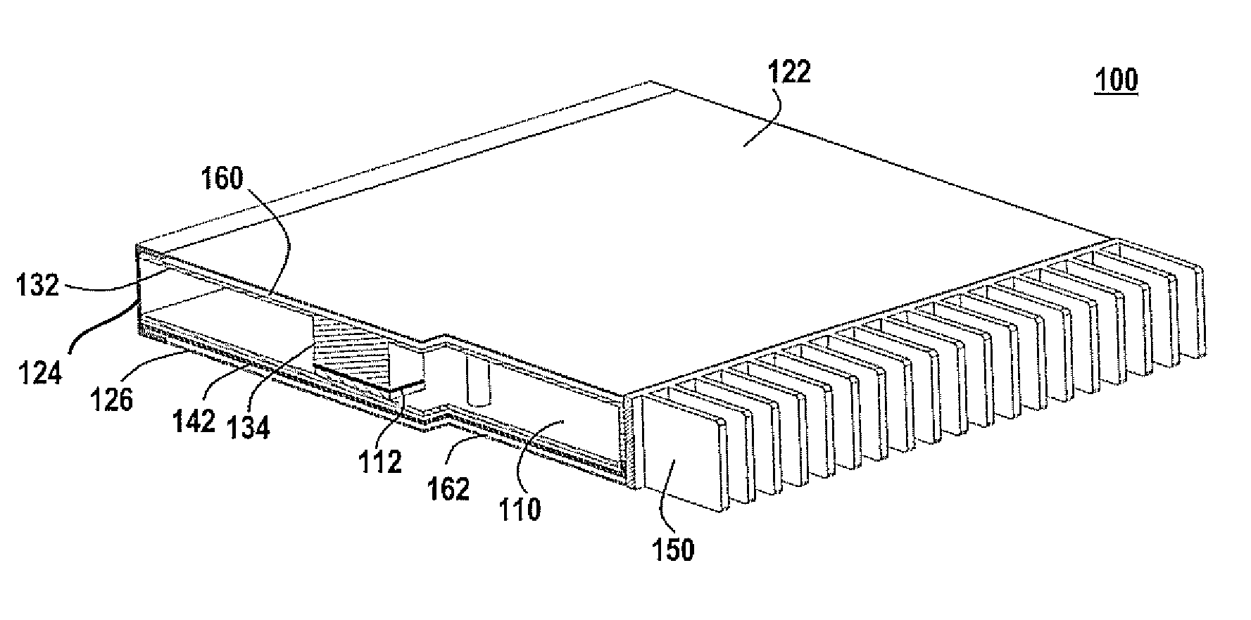
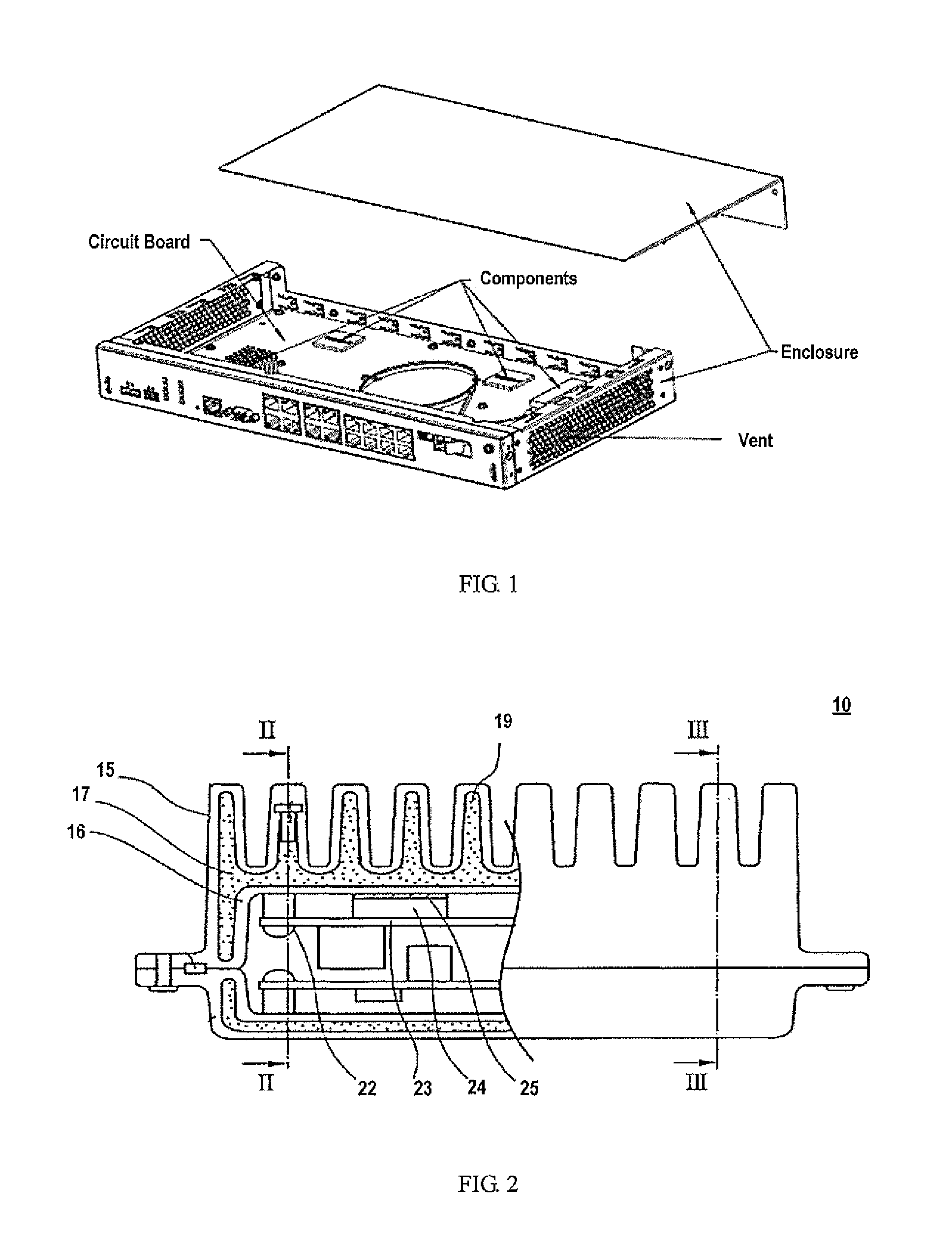
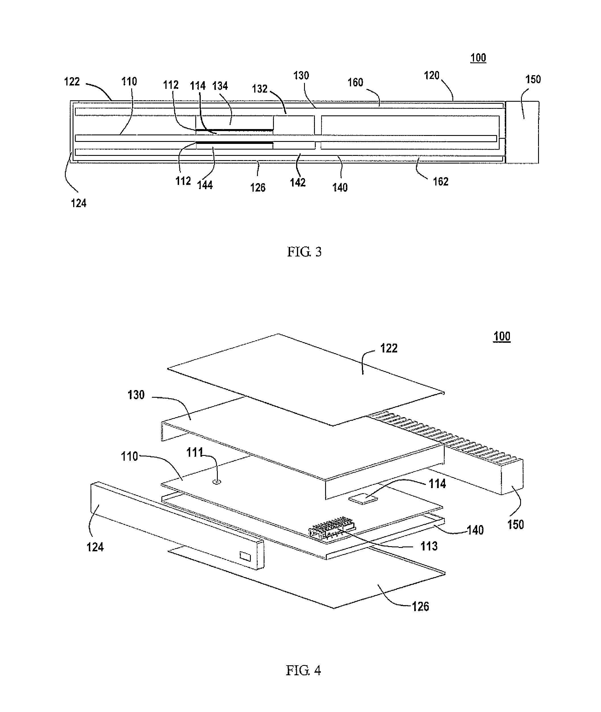
[0020]Embodiments of the present invention provide an electronic device having a novel heat-dissipating structure which will be detailed hereinafter by exemplary embodiments.

[0021]It should be appreciated that, while this specification contains many specific implementation details, they should not be construed as limitations on the scope of any invention or of what may be claimed, but rather as descriptions of features that may be specific to particular embodiments of particular inventions. Certain features that are described in this specification in the context of separate embodiments can also be implemented in combination in a single embodiment. Conversely, various features that are described in the context of a single embodiment can also be implemented in multiple embodiments separately or in any suitable sub-combination. Moreover, although features may be described above as acting in certain combinations and even initially claimed as such, one or more features from a claimed com...


PUM


Abstract

There is disclosed an electronic device having a heat-dissipating structure. The electronic device comprises a circuit board; a heat conduction plate arranged to face the circuit board, and dissipate heat generated by the circuit board only in a direction parallel to the heat conduction plate. According to the present invention, the electronic device is particular suitable for the application wherein the electronic device will be stacked up on another electronic device and requires no any forced convection arrangement such as a fan.

Description

TECHNICAL FIELD[0001]The present invention generally relates to the heat-dissipating technique, and more particularly, relates to an electronic device having a heat-dissipating structure.BACKGROUND[0002]Usually, the electronic device comprises a lot of electronic components which will generate heat during operations. Therefore, it requires heat-dissipating measures to be taken in the electronic device to release the heat generated by these electronic components. The heat-dissipating measures can usually be divided into two types, i.e., natural convection and forced convection. In general, the natural convection is a more preferable option than the forced convection in the field of, for example, telecommunication, because of its merits of high reliability, low cost, no noise, and etc.[0003]FIG. 1 schematically illustrates a conventional natural convection heat-dissipating structure of an electronic device, particularly a telecommunication device. As illustrated in FIG. 1, the telecom...

Claims


Application Information

Patent Timeline
IPC IPC(8): H05K7/20
CPCH05K7/20545H05K7/2039
Inventor SHI, XIUYIN, MIN
Owner TELEFON AB LM ERICSSON (PUBL)
Why Eureka
Try Eureka