

Ultrasonic signal coupler
- Summary
- Abstract
- Description
- Claims
- Application Information
AI Technical Summary
Benefits of technology
Problems solved by technology
Method used
Image

Examples
Embodiment Construction
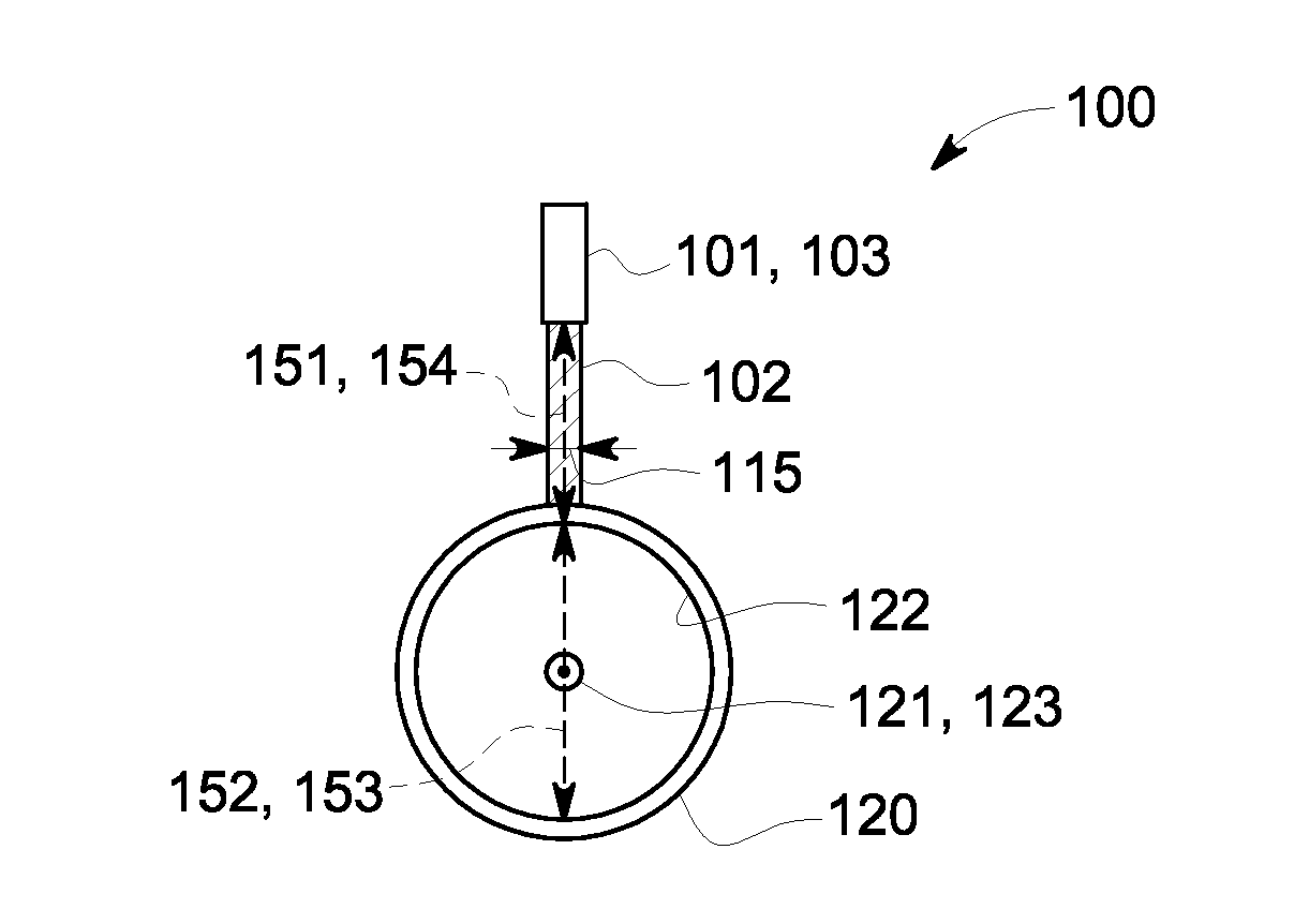
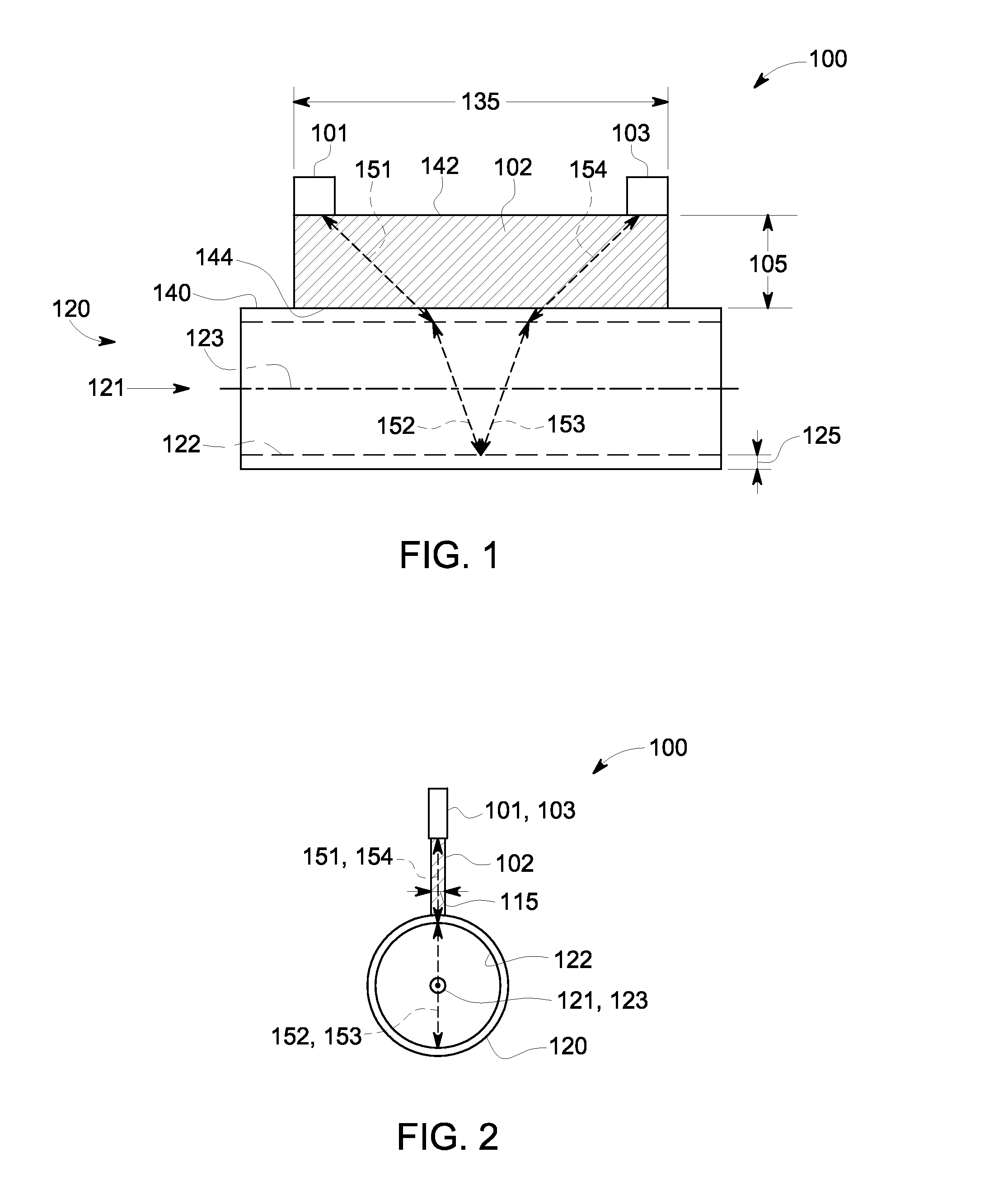
[0019]FIG. 1 and FIG. 2 illustrate a front and side view, respectively, of one embodiment of an ultrasonic coupler assembly 100, wherein ultrasonic transducers 101, 103, are attached to ultrasonic coupler 102, which, in turn, is attached to a pipe 120 carrying a fluid traveling in direction 121 therethrough, shown as traveling from left to right in the front view of FIG. 1. The ultrasonic transducers 101, 103 each transmit ultrasonic signals that travel along a representative ultrasonic signal path segment 151, 152, 153, 154, from each of the ultrasonic transducers 101, 103 to the other.
[0020]Each of the ultrasonic transducers 101, 103 is capable of emitting ultrasonic signals and detecting ultrasonic signals. For example, when ultrasonic transducer 101 emits an ultrasonic signal it travels along representative ultrasonic signal path segment 151 through the ultrasonic coupler 102 and pipe 120, then is refracted along representative ultrasonic signal path segment 152 by a fluid trave...
PUM
 Abstract
Description
Claims
Application Information