Autostereoscopic image display and method for driving the same

a technology of autostereoscopic image and display method, which is applied in the direction of instruments, computing, electric digital data processing, etc., can solve the problems of stereoscopic image degrade, image sticking, and liquid crystal molecules degrade,

Active Publication Date: 2014-05-08
LG DISPLAY CO LTD
View PDF13 Cites 13 Cited by
  • Summary
  • Abstract
  • Description
  • Claims
  • Application Information

AI Technical Summary

Benefits of technology

[0010]A method for driving the autostereoscopic display according to the embodiments of the invention includes causing a frame rate of the 3D cell to be greater than a frame rate of the display panel.

Problems solved by technology

When DC voltage is applied to liquid crystal molecules for a long time, the liquid crystal molecules are degraded due to an unwanted electrochemical reaction of the liquid crystal molecules, and image sticking is generated.
However, when the liquid crystal layer of the 3D cell is driven using the AC voltage, a kickback voltage varies depending on a polarity of the voltage applied to the liquid crystal layer of the 3D cell in the same manner as the liquid crystal display.
Even if an image displayed on the liquid crystal display has the excellent display quality, a stereoscopic image may be degraded due to the flicker of the switchable barrier or the switchable lens.

Method used


Image

  • Autostereoscopic image display and method for driving the same
  • Autostereoscopic image display and method for driving the same
  • Autostereoscopic image display and method for driving the same

Examples


second embodiment

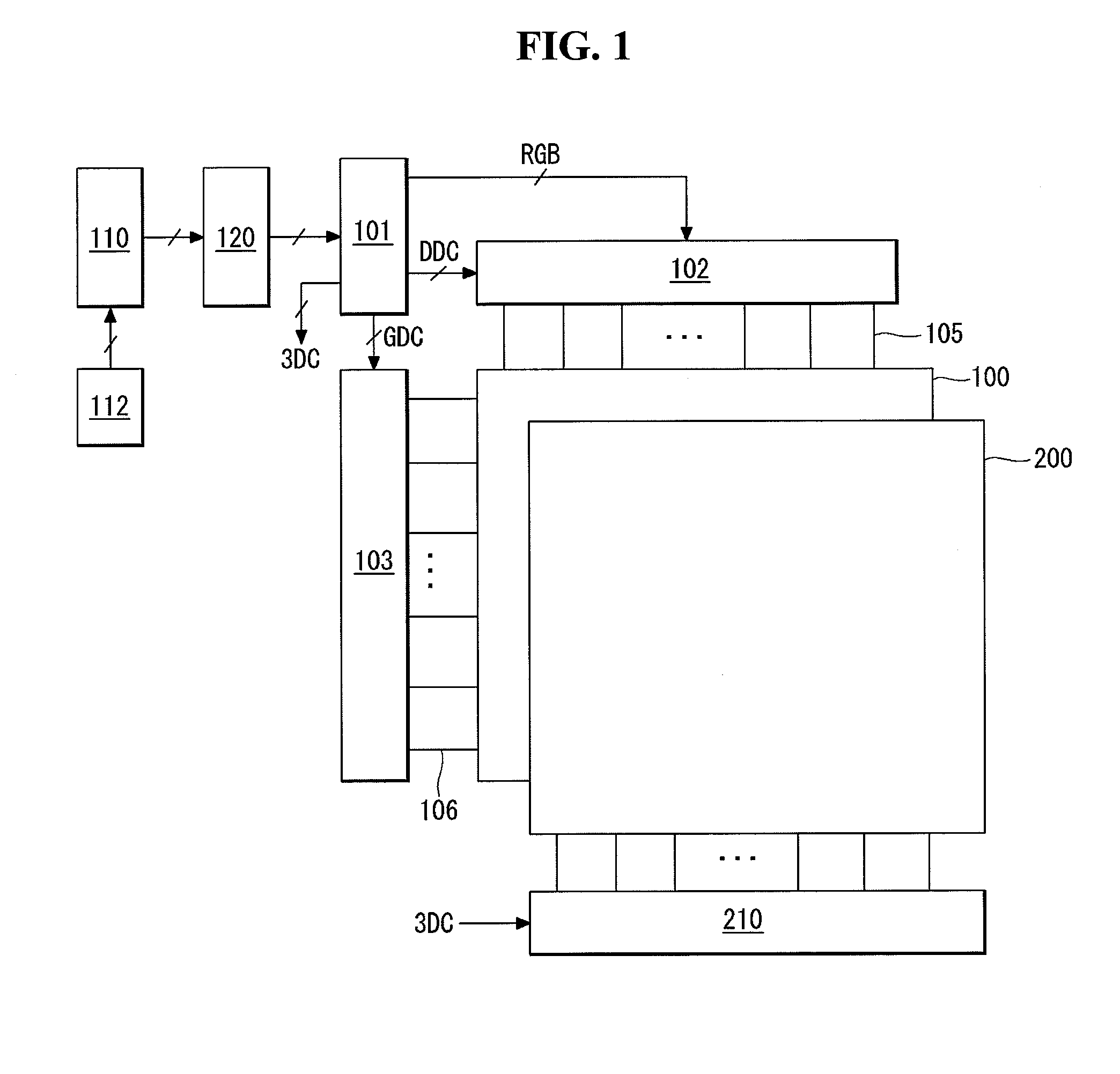
[0054]As shown in FIGS. 11 to 17, an autostereoscopic display according to the present invention can cause the frame rate of the 3D cell 200 to be greater than the frame rate of the display panel 100, so as to reduce the flicker of the 3D cell 200. In examples illustrated in FIGS. 11 to 17, while the frame rate of the display panel 100 is 120 Hz, the frame rate of the 3D cell 200 is 240 Hz and is two times greater than the frame rate of the display panel 100. In this instance, one frame period of the display panel 100 is 1 / 120 msec, and one frame period of the 3D cell 200 is 1 / 240 msec. Hereinafter, the frame period of the display panel 100 is referred to as a display frame period, and the frame period of the 3D cell 200 is referred to as a 3D cell frame period.

[0055]In the example illustrated in FIG. 7, when the barrier BAR of the 3D cell 200 is shifted, the white gray voltage is applied to the “1” electrode of the 3D cell 200 during odd-numbered display frame periods. Then, the bl...

fourth embodiment

[0067]As shown in FIGS. 19 to 21, an autostereoscopic display according to the present invention includes, for example, a driving voltage of a 3D cell and a liquid crystal response curve of a display panel.

[0068]As shown in FIG. 19, the driving voltages Vdrv, which are set to the voltages of different polarities, may be applied to the adjacent lines of the 3D cell 200. For example, the driving voltage Vdrv shown in an upper waveform diagram of FIGS. 19 to 21 may be applied to the cells C1 to C3 positioned on the odd-number lines of FIG. 18. Further, the driving voltage Vdrv shown in a lower waveform diagram of FIGS. 19 to 21 may be applied to the cells C4 to C6 positioned on the even-number lines of FIG. 18.

[0069]Accordingly, one of the advantages of the embodiments of the present invention is that the frame rate of the 3D cell to can be greater than the frame rate of the display panel, thereby preventing the flicker of the 3D cell.


PUM


Abstract

An autostereoscopic display and a method for driving the same are discussed. The autostereoscopic display according to an embodiment includes a display panel displaying data of a left eye image and data of a right eye image and a three-dimensional (3D) cell which is positioned on the display panel or is embedded in the display panel and separates optical axes of the left eye image and the right eye image. A frame rate of the 3D cell is greater than a frame rate of the display panel.

Description

[0001]This application claims the priority benefit of Korean Patent Application No. 10-2012-00126043 filed on Nov. 8, 2012, the entire contents of which is incorporated herein by reference for all purposes as if fully set forth herein.BACKGROUND OF THE INVENTION[0002]1. Field of the Invention[0003]Embodiments of the invention relate to an autostereoscopic display and a method for driving the same.[0004]2. Discussion of the Related Art[0005]As stereoscopic image reproduction technology is applied to display devices, such as a television and a monitor, with the development of stereoscopic image display technology, now is the age in which people can easily view three-dimensional (3D) stereoscopic images even at home. A 3D display may be classified into a stereoscopic display and an autostereoscopic display called a glasses-free 3D display. The stereoscopic display displays a parallax image between the left and right eyes on a direct-view display or a projector through changes in a pola...

Claims


Application Information

Patent Timeline
Patent Type & Authority Applications(United States)
IPC IPC(8): H04N13/04G02B30/28G02B30/30
CPCH04N13/0402G09G3/003G09G3/2022G09G2320/0247G09G2340/16G09G3/3614G09G2320/0204H04N13/305H04N13/324H04N13/315H04N13/398G02B30/28G02B30/30G09G3/36G02B30/27
Inventor CHUNG, BOGYUNAN, CHUNGHWANCHIN, KYUNGAHLEE, TAEJOON
Owner LG DISPLAY CO LTD
Why Eureka
Try Eureka