Spoke Clip For Electroluminescent Wire Display

a technology of electroluminescent wire and spokes, which is applied in the direction of cycle equipment, lighting and heating apparatus, lighting support devices, etc., can solve the problems of unnecessarily complicated system, unnecessary side illumination of wheels, and relatively complicated multi-part clips to manipulate and secure to the spokes, and achieves more aerodynamic and more secure

Inactive Publication Date: 2014-05-08
HALEK JUSTIN
View PDF3 Cites 1 Cited by
  • Summary
  • Abstract
  • Description
  • Claims
  • Application Information

AI Technical Summary

Benefits of technology

[0008]When the clip is applied to a spoke, the spoke nut socket radially receives and loosely engages the spoke. Sliding the clip outwardly to the wheel rim along the spoke causes the spoke nut socket to axially mate with and tightly engage the spoke nut. The result is that the clip can be rotated freely when initially mounted on a spoke, but resists rotation when engaged with the spoke nut.
[0009]In its second aspect, the clip is mounted on a spoke nut, and rotated to a wire-engaging position in which the stem is generally parallel to the plane of the wheel, and in which the wire-mounting arm is generally perpendicular to the plane of the wheel. An electroluminescent (EL) wire is clipped to the slot in the wire-mounting arm, which positions the wire relative to the adjacent spokes, running generally in or parallel to the plane of the wheel. Mounting multiple clips around the wheel allows the wire to be mounted in whatever pattern desired in a plane generally parallel to the plane of the wheel, positioned close to the spokes.
[0010]The resulting illuminated display on the bike wheel is more secure, more aerodynamic, and provides a more steady or solid light pattern (without flickering) than prior art devices and systems. The resulting illuminated display is just as visible when stationary as when moving.

Problems solved by technology

While the Revolights™ LED rings produce a useful ground level headlight / taillight effect at the leading / trailing edges of the front and rear wheels, in addition to side illumination for visibility by others, the multi-part clips are relatively complicated to manipulate and secure to the spokes, and the LED rings and associated hardware needed to align, install, and operate the lights make a system that is unnecessarily complicated and expensive for simple side illumination of the wheels.

Method used


Image

  • Spoke Clip For Electroluminescent Wire Display
  • Spoke Clip For Electroluminescent Wire Display
  • Spoke Clip For Electroluminescent Wire Display

Examples


Embodiment Construction

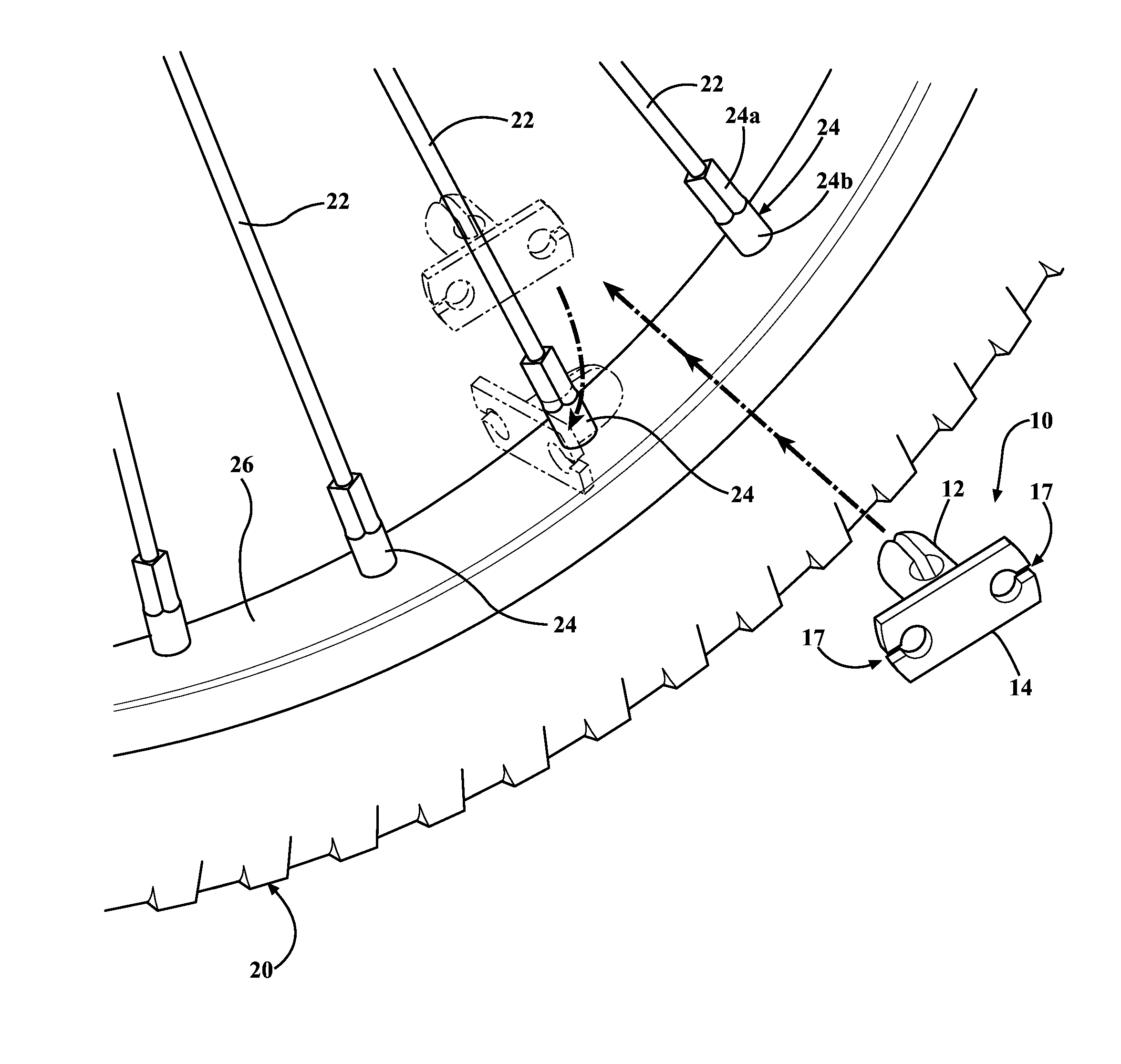
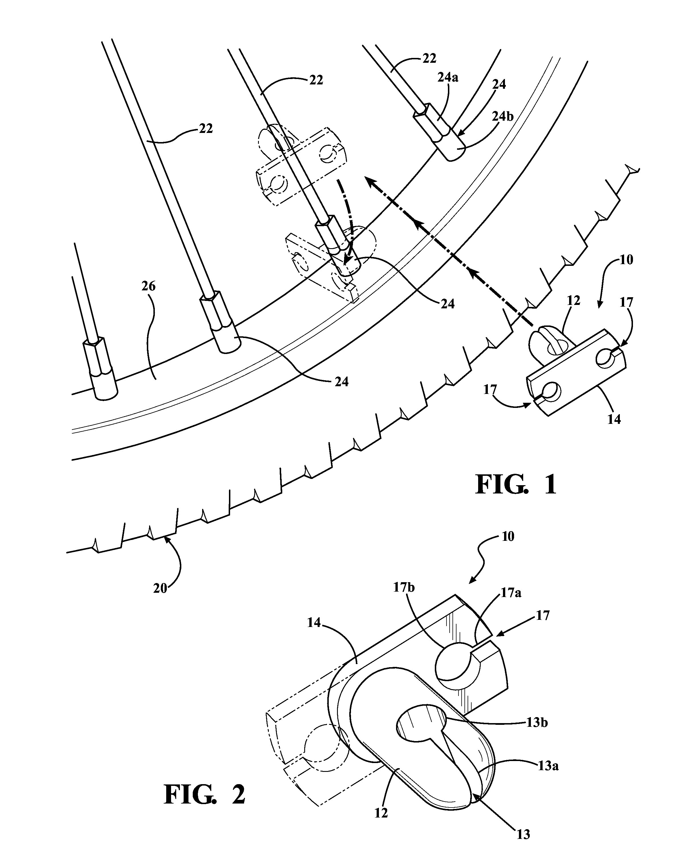
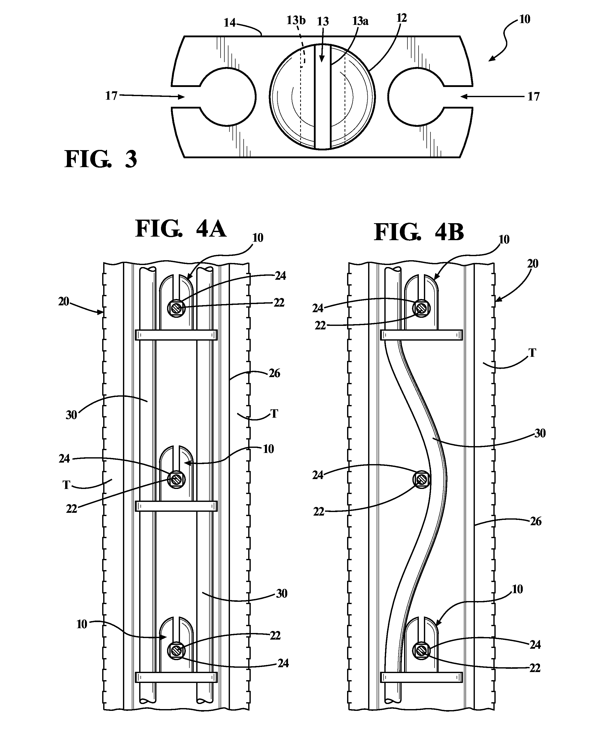
[0017]Referring first to FIGS. 1 through 3, a spoke clip 10 is shown in exemplary form in order to teach how to make and use the claimed invention. Spoke clip 10 is designed to be attached to the spokes 22 of a bike wheel 20, and in particular to be secured in use to the spoke nuts 24 that join the spokes to the rim 26 of the wheel. Bike wheel 20 in the illustrated example should be understood to represent primarily bicycle wheels, but also scooter, motorcycle, and other types of similarly-spoked wheel, without limitation.

[0018]Spoke clip 10 includes a spoke-mounting stem 12 and a wire-holding arm 14 generally perpendicular to the stem. Although clip 10 is illustrated as a generally T-shaped clip capable of holding two wires, one on each side of the stem, it will be understood that generally L-shaped clips for holding a single wire are also possible. FIG. 2 shows one of the wire-holding arms 14 in phantom, such that the solid line portion of the drawing represents such an L-shaped c...


PUM


Abstract

A spoke clip adapted to be removably secured to a spoke nut of a bicycle wheel, and further adapted to mount an illuminated wire to the spokes of the bicycle wheel. The clips are generally L- or T-shaped, with a slotted stem having a spoke-admitting initial width and terminating in a spoke nut socket, and a wire-mounting arm perpendicular to the stem and adapted to receive and hold a wire in parallel to the axis of the stem. The invention also includes the illuminated wire display created by securing an illuminated wire in a planar array to the spokes adjacent the wheel rim using a plurality of the spoke clips.

Description

RELATED APPLICATIONS / PRIORITY BENEFIT CLAIM[0001]This application claims the benefit of U.S. Provisional Application No. 61 / 723,076, filed Nov. 6, 2012 by the same inventor (Halek), the entirety of which provisional application is hereby incorporated by reference.FIELD[0002]The subject matter of the present application is in the field of electroluminescent wire displays for bike wheels, and in particular devices for securing such wire to a bike wheel.BACKGROUND[0003]Many devices for illuminating bicycles (bikes) at night are known. One example is the Bikeglow™ safety light, consisting of an electroluminescent wire and a battery power unit adapted to be mounted on a bike. Normally the wire is wound around portions of the bike frame, away from moving parts and cables; however, I have seen the electroluminescent wire taped to the spokes of a bike wheel, with the power unit secured to rotate with the wheel between the spokes.[0004]The Revolights™ bike lighting system consists of two nar...

Claims


Application Information

Patent Timeline
Patent Type & Authority Applications(United States)
IPC IPC(8): B62J6/20F16B17/00
CPCF16B17/00B62J6/20F16B2/22F21V21/08F21V21/088Y10T24/44
Inventor HALEK, JUSTIN
Owner HALEK JUSTIN
Why Eureka
Try Eureka