
Optical fiber-based distributed radio frequency (RF) antenna systems supporting multiple-input, multiple-output (MIMO) configurations, and related components and methods

a distributed radio frequency (rf) antenna and optical fiber technology, applied in the direction of radio-over-fiber, diversity/multi-antenna systems, spatial transmit diversity, etc., can solve the problem that optical fiber-based distributed antenna systems may have limitations on performance (i.e., data rate) based, and achieve the effect of improving data communication rate, improving communication performance, and improving spectral efficiency

Inactive Publication Date: 2014-05-08
CORNING OPTICAL COMM LLC
View PDF20 Cites 272 Cited by
  • Summary
  • Abstract
  • Description
  • Claims
  • Application Information

AI Technical Summary

Benefits of technology

The patent describes optical fiber-based distributed antenna systems that support MIMO communications configurations. These systems can improve data communication rates without requiring additional bandwidth or transmit power. When providing MIMO communications configurations, the system can use existing capacity of components or create separate communication paths, which consumes additional system resources. The technical effect of this patent is to allow for improved MIMO communications configurations without consuming additional capacity of the system and reducing overall capacity of the system.

Problems solved by technology

Optical-fiber based distributed antenna systems may have limitations on performance (i.e., data rate) based on the particular components and configurations chosen for the system.

Method used


Image

  • Optical fiber-based distributed radio frequency (RF) antenna systems supporting multiple-input, multiple-output (MIMO) configurations, and related components and methods
  • Optical fiber-based distributed radio frequency (RF) antenna systems supporting multiple-input, multiple-output (MIMO) configurations, and related components and methods
  • Optical fiber-based distributed radio frequency (RF) antenna systems supporting multiple-input, multiple-output (MIMO) configurations, and related components and methods

Examples


Embodiment Construction

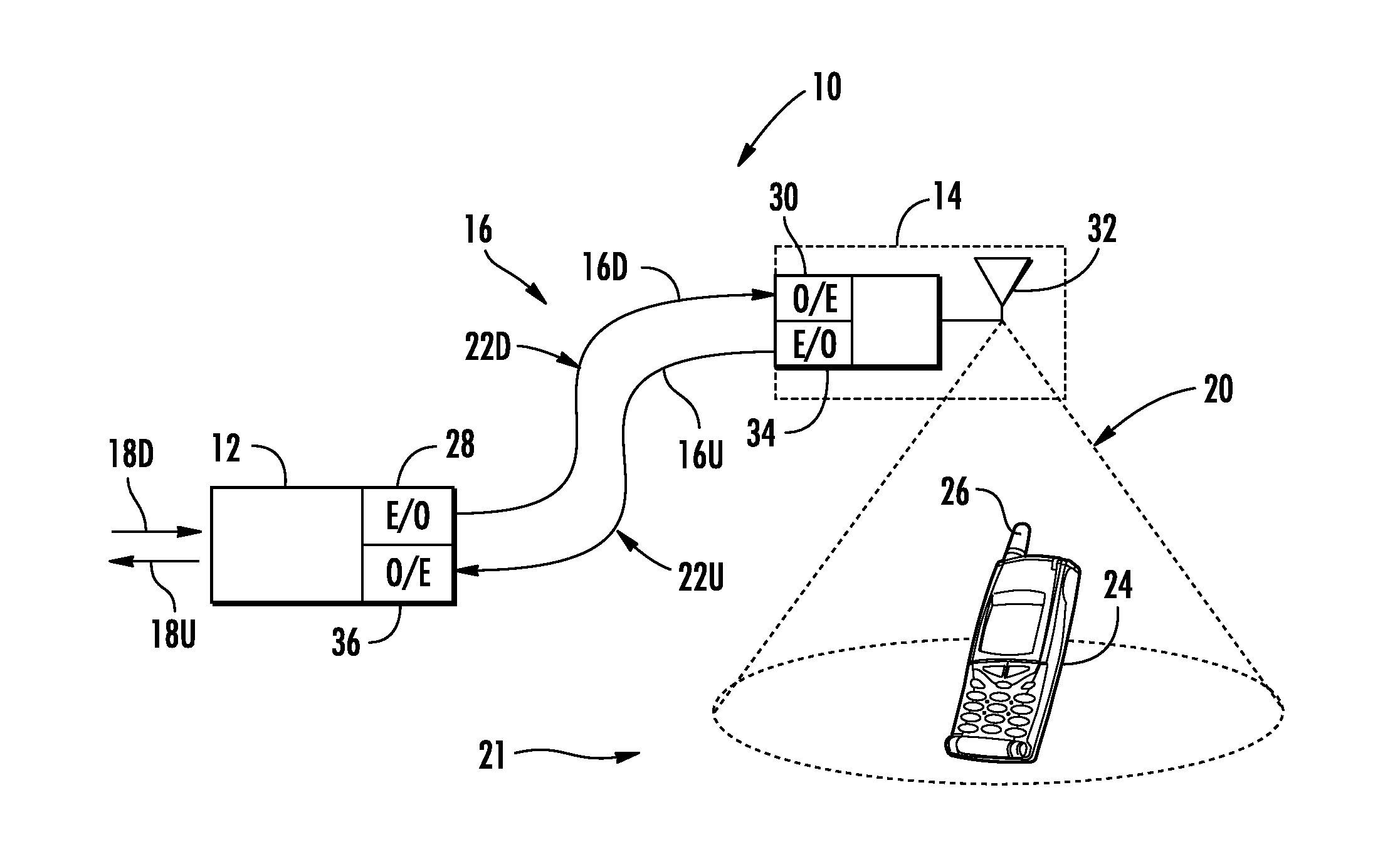
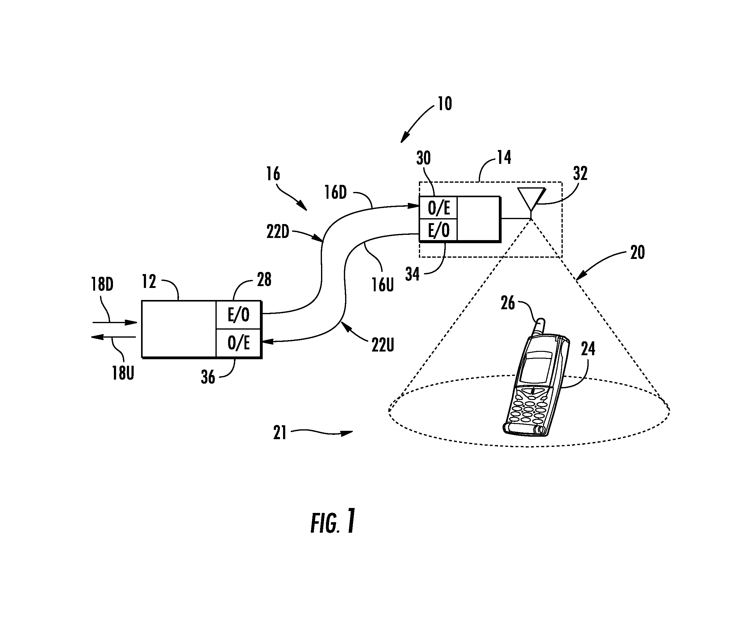
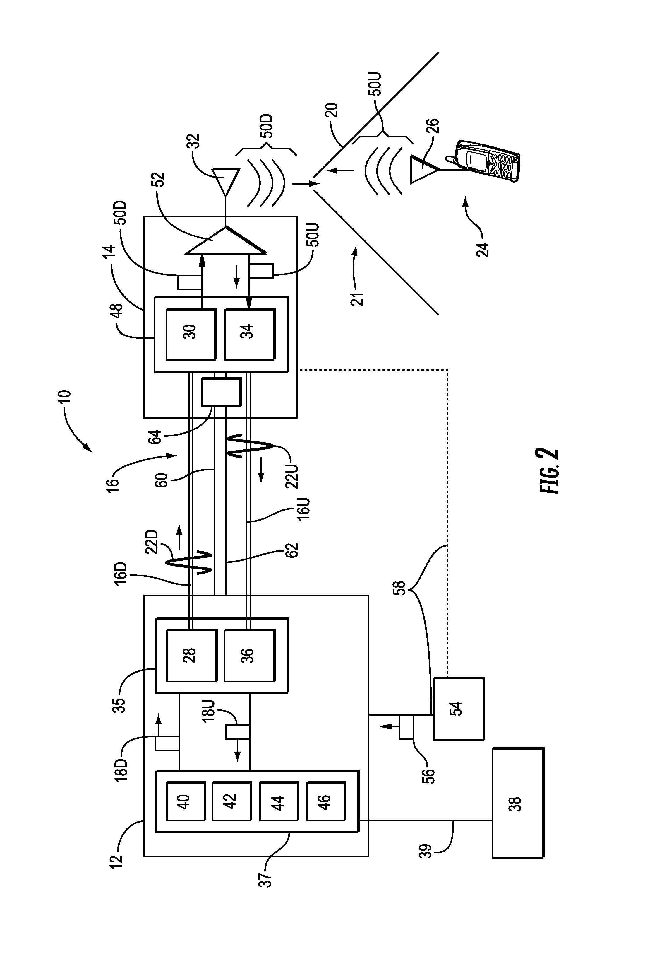
[0011]Embodiments disclosed in the detailed description include optical fiber-based distributed antenna systems that support multiple-input, multiple-output (MIMO) antenna configurations and communications. MIMO communications configurations involve the use of multiple antennas at both the transmitter and a receiver to improve communications performance. MIMO can offer significant increases in data communications rates without requiring additional bandwidth or transmit power by higher spectral efficiency (i.e., more data per second per hertz of bandwidth) ad link reliability or diversity to reduce fading. Embodiments disclosed herein also include optical fiber-based distributed antenna system that can be flexibly configured to support or not support MIMO communications configurations. When configured to support MIMO communications configurations, the optical fiber-based distributed antenna systems can be provided that allow for MIMO configurations without consuming additional capaci...


PUM


Abstract

Optical fiber-based distributed antenna systems that support multiple-input, multiple-output (MIMO) antenna configurations and communications. Embodiments disclosed herein include optical fiber-based distributed antenna system that can be flexibly configured to support or not support MIMO communications configurations. In one embodiment, first and second MIMO communication paths are shared on the same optical fiber using frequency conversion to avoid interference issues, wherein the second communication path is provide to a remote extension unit to remote antenna unit. In another embodiment, the optical fiber-based distributed antenna systems may be configured to allow to provide MIMO communication configurations with existing components. Existing capacity of system components are employed to create second communication paths for MIMO configurations, thereby reducing overall capacity, but allowing avoidance of frequency conversion components and remote extension units.

Description

PRIORITY APPLICATION[0001]This application is a continuation of PCT Application No. PCT / US2011 / 43405, filed Jul. 8, 2011, which claims the benefit of priority under 35 U.S.C. §119 of U.S. Provisional Application No. 61 / 363,007 filed on Jul. 9, 2010, entitled “Optical Fiber-based Distributed Radio Frequency (RF) Communications Systems, and Related Components and Methods,” the content of which is relied upon and incorporated herein by reference in its entirety.RELATED APPLICATIONS[0002]The present application is related to International Application No. PCT / US11 / 34733 filed on May 2, 2011, entitled “Optical Fiber-based Distributed Communications Systems, and Related Components and Methods,” which is incorporated herein by reference in its entirety, and which claims priority to U.S. Provisional Patent Application Ser. No. 61 / 330,383 filed on May 2, 2010, entitled “Optical Fiber-based Distributed Communications Systems, and Related Components and Methods.”[0003]The present application is...

Claims


Application Information

Patent Timeline
Patent Type & Authority Applications(United States)
IPC IPC(8): H04B10/2575H04B7/04
CPCH04B7/0413H04B10/25753
Inventor BERLIN, IGORCUNE, WILLIAM PATRICKKEDZIORA, JESSICA JOYSAUER, MICHAELSCHMIDT, GERALD BERNHARTSCHWEIKER, WOLFGANG GOTTFRIED TOBIAS
Owner CORNING OPTICAL COMM LLC
Learn More