Monitoring method and camera

Active Publication Date: 2014-05-15
AXIS
View PDF0 Cites 2 Cited by
  • Summary
  • Abstract
  • Description
  • Claims
  • Application Information

AI Technical Summary

Benefits of technology

[0020]The step of determining a key position may comprise setting the key position to a position of a highest temperature of the suspicious object. The temperature of a person is usually highest in the head region which means that this would often be a correct estimation of where the body of a person is located. To increase robustness it would be possible to set the highest temperature position to a mean or median value of e.g. the ten highest temperature positions. It would also be possible to

Problems solved by technology

When the person working at the desk or counter is serving a customer, it might be difficult for him or her to keep track of other persons app

Method used


Image

  • Monitoring method and camera
  • Monitoring method and camera
  • Monitoring method and camera

Examples


Embodiment Construction

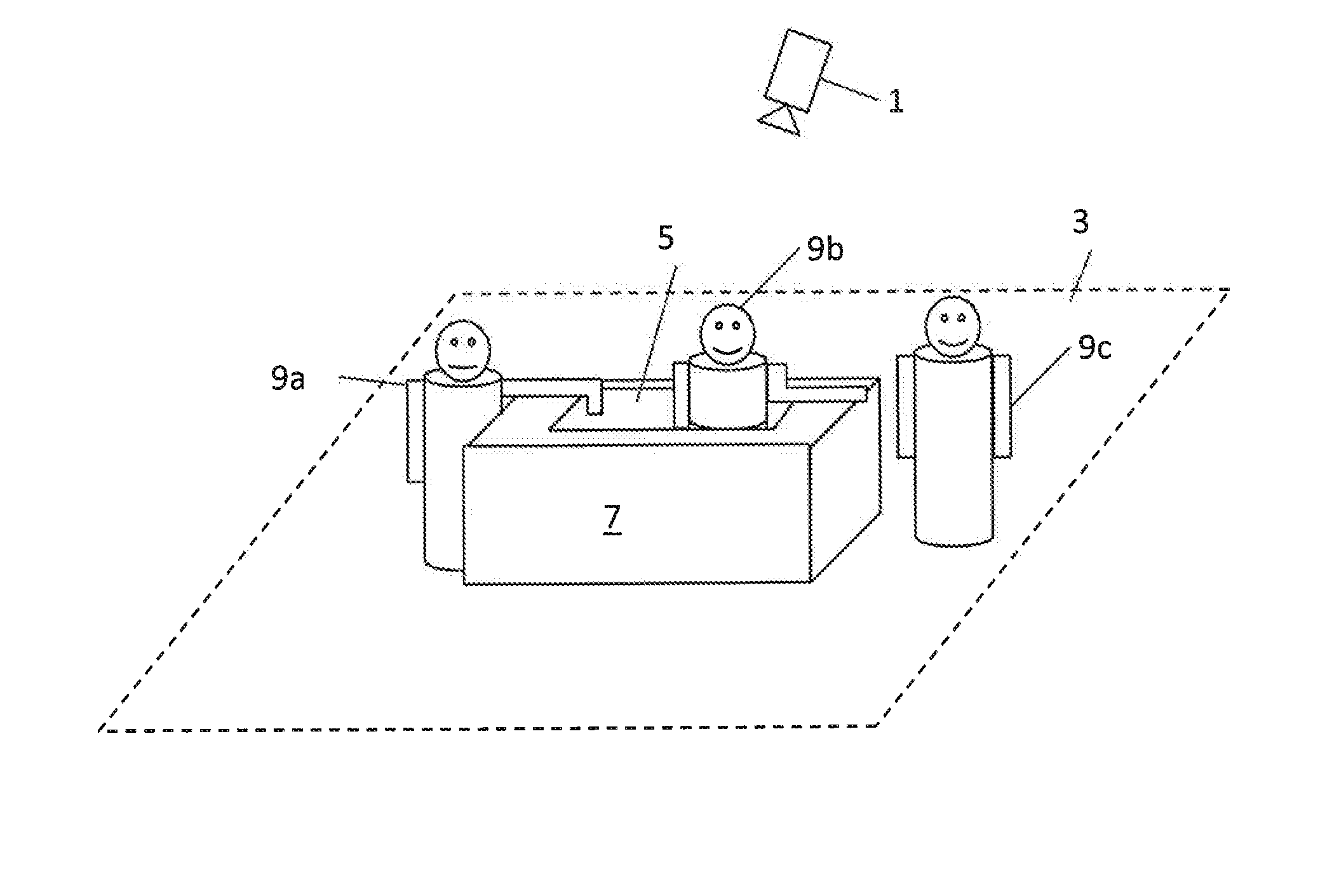
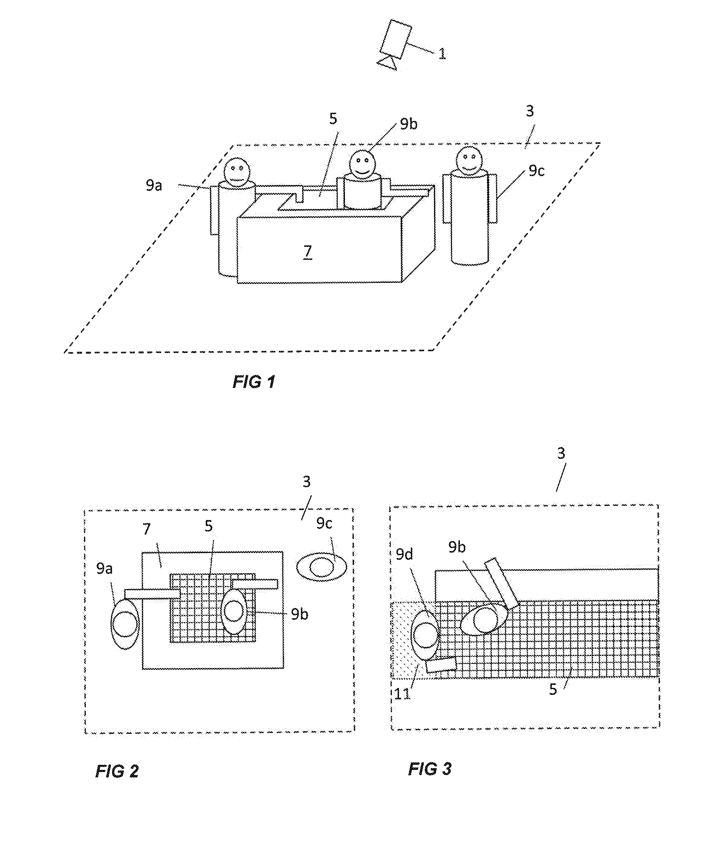
[0033]FIG. 1 illustrates an exemplifying situation where a monitoring camera 1 is arranged to monitor an area 3. The monitoring camera 1 could symbolize a group of monitoring cameras with differing imaging capabilities or a camera including several image sensors. The camera or cameras may e.g. include an image sensor capturing visible light images, a thermal sensor producing images of the temperature within the monitored area, or an image sensor capturing three-dimensional images, e.g. a TOF, time-of-flight, image sensor which gives an image of distance to different pixels, from which it is possible to calculate the depth or height of the monitored area and objects therein.

[0034]The monitored area 3 includes a protected zone 5, in the illustrated example defined by a physical element 7, e.g. in the form of a counter. Objects 9a, 9b, and 9c are present within the monitored area 3. FIG. 2 is a view from above of the situation illustrated in FIG. 1. In other words, FIG. 2 schematically...


PUM


Abstract

A method and a system is provided for monitoring an area by a monitoring camera (1). A protected zone (5) is defined within the monitored area (2) and a suspicious object (9a, 9b) is detected as an object present both inside and outside the protected zone. A key position of the suspicious object is determined, and it is determined if the key position is inside or outside the protected zone (5). If the key position is outside the protected zone a first action is triggered.

Description

CROSS REFERENCE TO RELATED APPLICATION[0001]This application claims the benefit of EPC Application No. 12192217.3, filed Nov. 12, 2012 and U.S. provisional application No. 61 / 726,812, filed Nov. 15, 2012, which are incorporated herein by reference as if fully set forth.TECHNICAL FIELD[0002]The present invention relates to a method and a system for monitoring an area by a monitoring camera.BACKGROUND[0003]Surveillance cameras are currently used in many different applications, for monitoring environments both indoors and outdoors. Cameras may e.g. be used for monitoring areas where a person is serving customers from behind a counter, and where the inside of the counter may be used as storage for items or equipment where access should be restricted to the person manning the counter. Examples of such environments could be hotel front desks, bank office counters, reception desks, bars, fast food counters, cashier desks at gas stations, or check-in counters at airports. Another example is...

Claims


Application Information

Patent Timeline
IPC IPC(8): G06K9/00
CPCG08B13/1968G08B13/19613G08B13/19652G06K9/00771G06V20/52G06T7/00H04N7/18
Inventor GUSTAFSSON, DANIELSAGEFALK, WILLYKAHRSTROM, JONATANTRAFF, GUSTAV
Owner AXIS
Why Eureka
Try Eureka