Lever-type connector

a connector and lever-type technology, applied in the direction of coupling device connection, coupling parts engagement/disengagement, electrical apparatus, etc., can solve the problems of not being able to easily mount the cover, the lever lever and the slider rack are not smoothly engaged, etc., to achieve the effect of more reliably avoiding

Active Publication Date: 2014-05-15
SUMITOMO WIRING SYST LTD
View PDF6 Cites 22 Cited by
  • Summary
  • Abstract
  • Description
  • Claims
  • Application Information

AI Technical Summary

Benefits of technology

[0008]The lever preferably is formed with a stopper tooth for preventing the slider from moving in a direction opposite to the moving direction of the cover by coming into contact with the leading rack tooth substantially facing in the moving direction of the cover out of the rack teeth of the slider at the first position in a state where the cover is at the engageable position and the lever is at the standby position. Thus, even if an external force should be applied to the slider when the slider is at the first position, a situation where the slider is inadvertently moved in a direction opposite to the moving direction of the cover can be avoided.
[0009]A stoppe

Problems solved by technology

However, if there is a relative displacement between the slider and the lever when the cover is mounted, it leads to a problem that

Method used


Image

  • Lever-type connector
  • Lever-type connector
  • Lever-type connector

Examples


Embodiment Construction

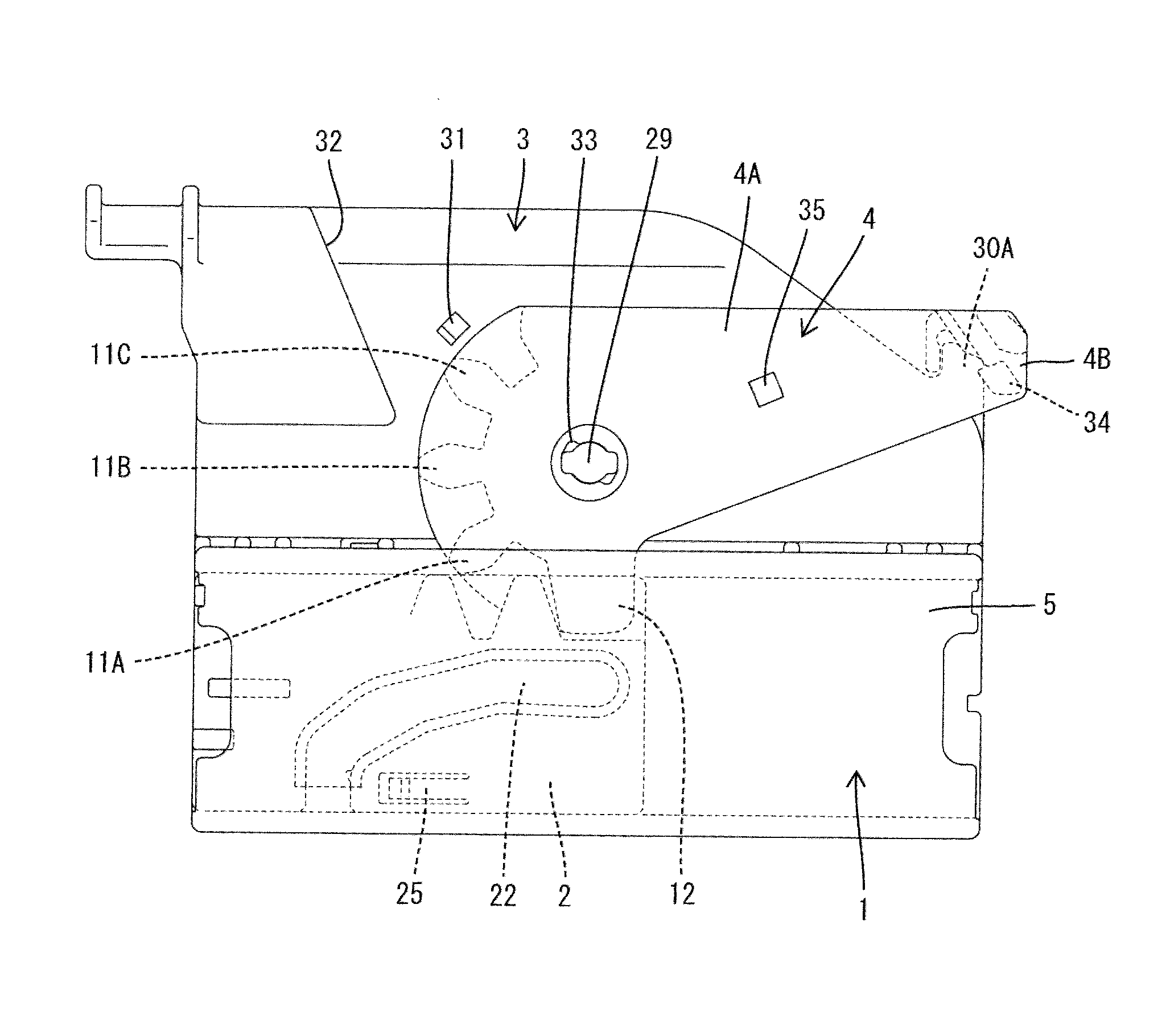
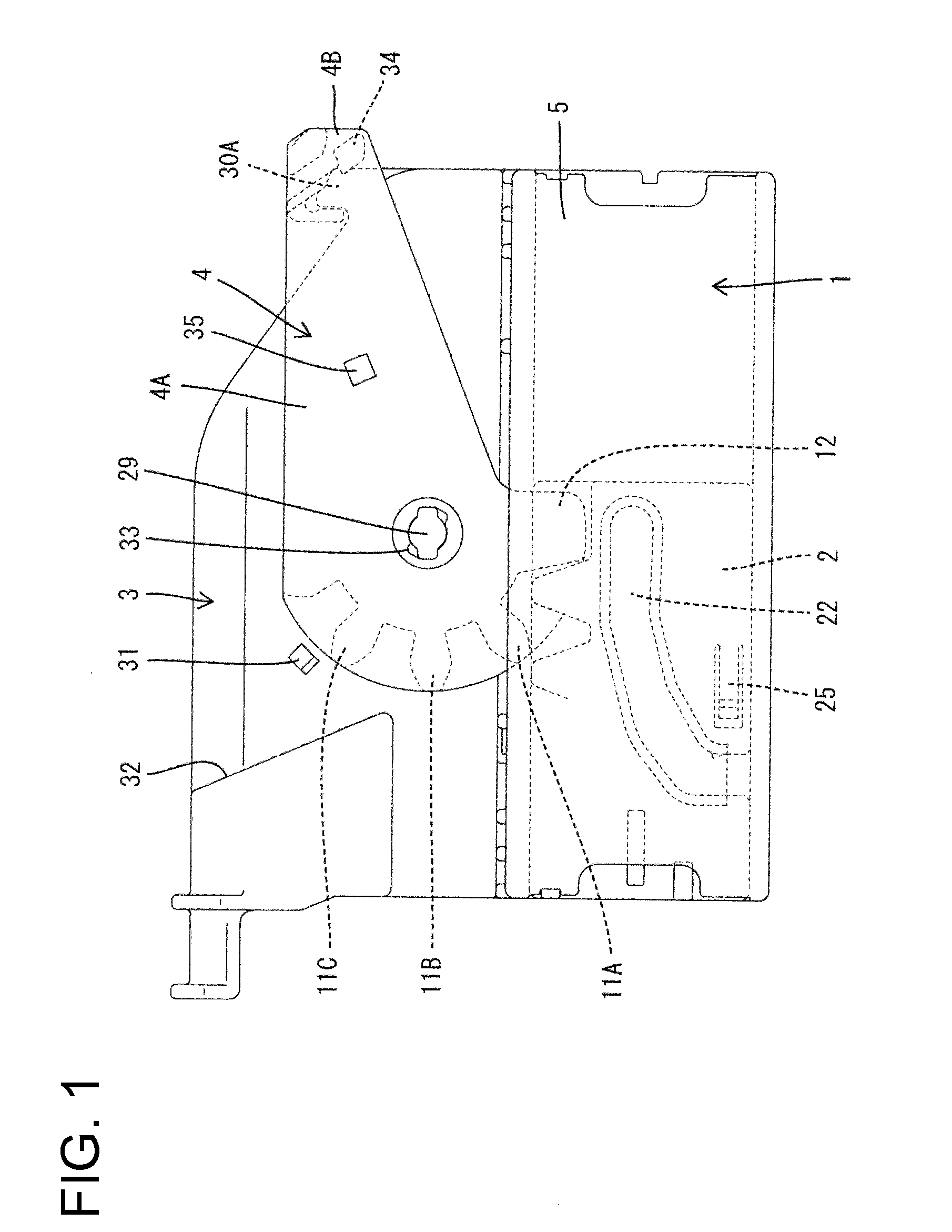
[0031]The lever-type connector of this embodiment is provided with a female housing 1, sliders 2 movably mounted on the housing 1, a cover 3 for covering wires W drawn out from the housing 1, and a lever 4 rotatably mounted on the cover 3.

[0032]Note that, in the following description, terms relating to “upper and lower sides” and “left and right sides” are based on FIG. 1.

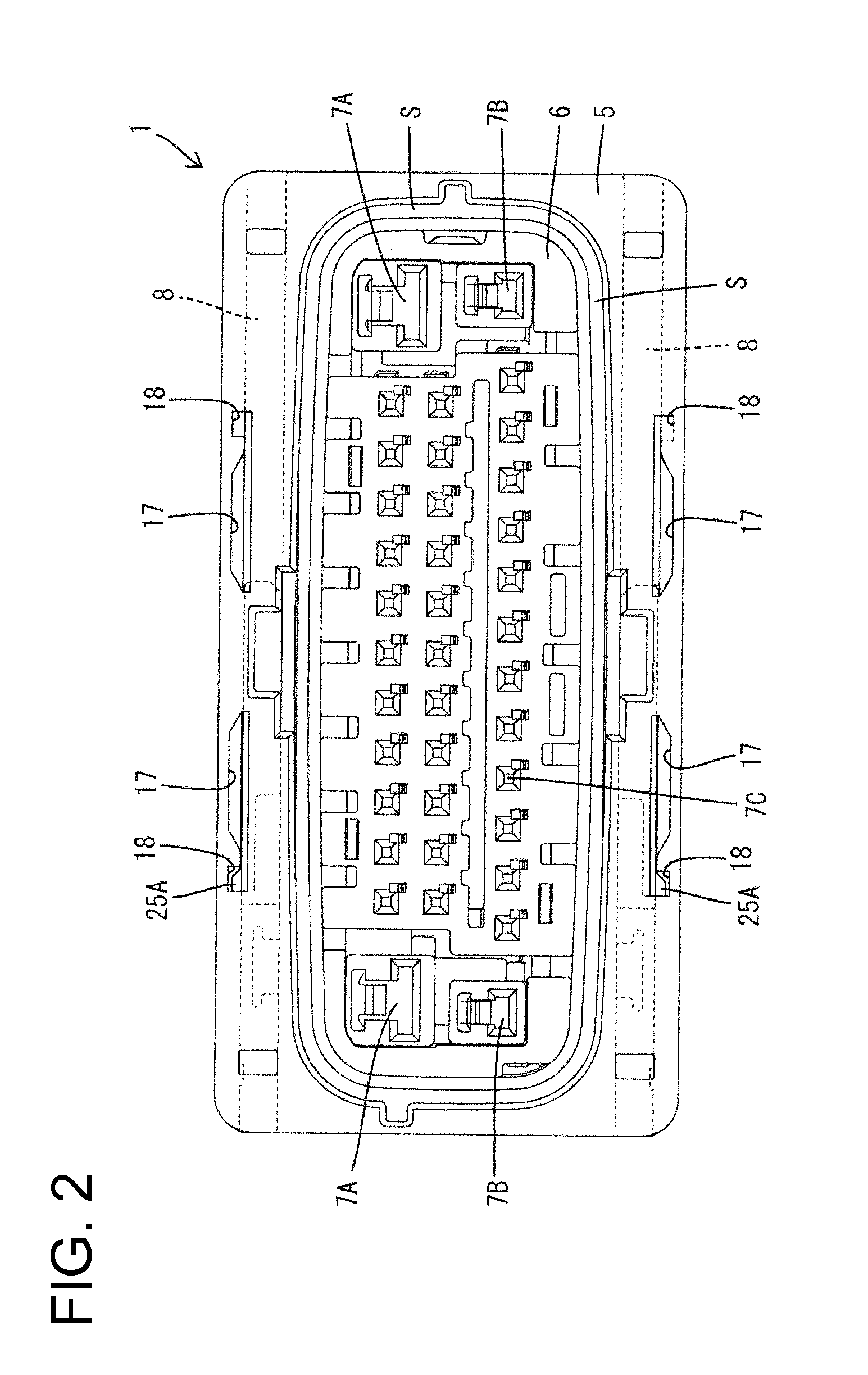
[0033]The housing 1 is made of synthetic resin and, as shown in FIG. 2, has a rectangular outer tube 5 and an inner tube 6 at least partly in the outer tube 5. A connection space S is formed around the inner tube 6 and between the tubes 5, 6 for receiving a mating connector. As shown in FIGS. 2 and 3, cavities 7A to 7C are formed in the inner tube 6 for accommodating terminal fittings T. The cavities 7A to 7C are open vertically in connecting directions. The terminal fittings T are insertable from above and mating terminal fittings in the mating male connector M are insertable from below.

[0034]The cavities 7A to 7C...


PUM


Abstract

A lever (4) mounted on a cover (3) is held at a standby position and, in that state, the cover (3) is fitted to a housing (1) in a connecting direction to a position where the cover (3) is not aligned with the housing (1). At this position, gear teeth of the lever (4) and rack teeth of sliders (2) do not interfere with each other and are not engaged. If the cover (3) is subsequently moved in a direction perpendicular to the connecting direction via a guiding action of the engagement of guide receiving portions (9) of the connector housing (1) and U-shaped guide portions (15) formed on the cover (3), the cover (3) is smoothly mounted at a proper mounting position. At this time, since the guide portions (15) vertically sandwich the guide receiving portions (9), upward detachment of the cover (3) is prevented.

Description

BACKGROUND[0001]1. Field of the Invention. The invention relates to a lever-type connector.[0002]2. Description of the Related Art. U.S. Pat. No. 8,246,365 discloses a connector having a force multiplying function by a lever and a slider. The slider is provided in a housing of the connector and movable in directions perpendicular to a connecting direction to a mating connector. Further, a cover for accommodating wires drawn out from the housing is mounted on the housing and the lever is rotatably mounted on the cover. The lever is formed with a gear and the slider is formed with a rack engageable with the gear. Further, the slider is formed with a cam groove for guiding a cam pin provided on the mating connector.[0003]If the lever is rotated in a state where the two connectors are lightly fitted, the slider moves via the engagement between the gear and rack and the cam pin is guided by the cam groove, whereby the two connectors are connected.[0004]The above cover is mounted by being...

Claims


Application Information

Patent Timeline
IPC IPC(8): H01R13/629
CPCH01R13/62944H01R13/516H01R13/62955H01R13/62977
Inventor ITOU, MASATOSHIHATA, TAKAOKOBAYASHI, TOMOHIKO
Owner SUMITOMO WIRING SYST LTD
Why Eureka
Try Eureka