
Apparatus and method for driving LED display panel

a technology of led display panel and led light, which is applied in the direction of electrical apparatus, electric variable regulation, instruments, etc., can solve the problems of short pulses and/or accompanying with pwm ringing, signal distorted, and loss of pwm signal

Active Publication Date: 2014-05-22
SCT
View PDF3 Cites 16 Cited by
  • Summary
  • Abstract
  • Description
  • Claims
  • Application Information

AI Technical Summary

Benefits of technology

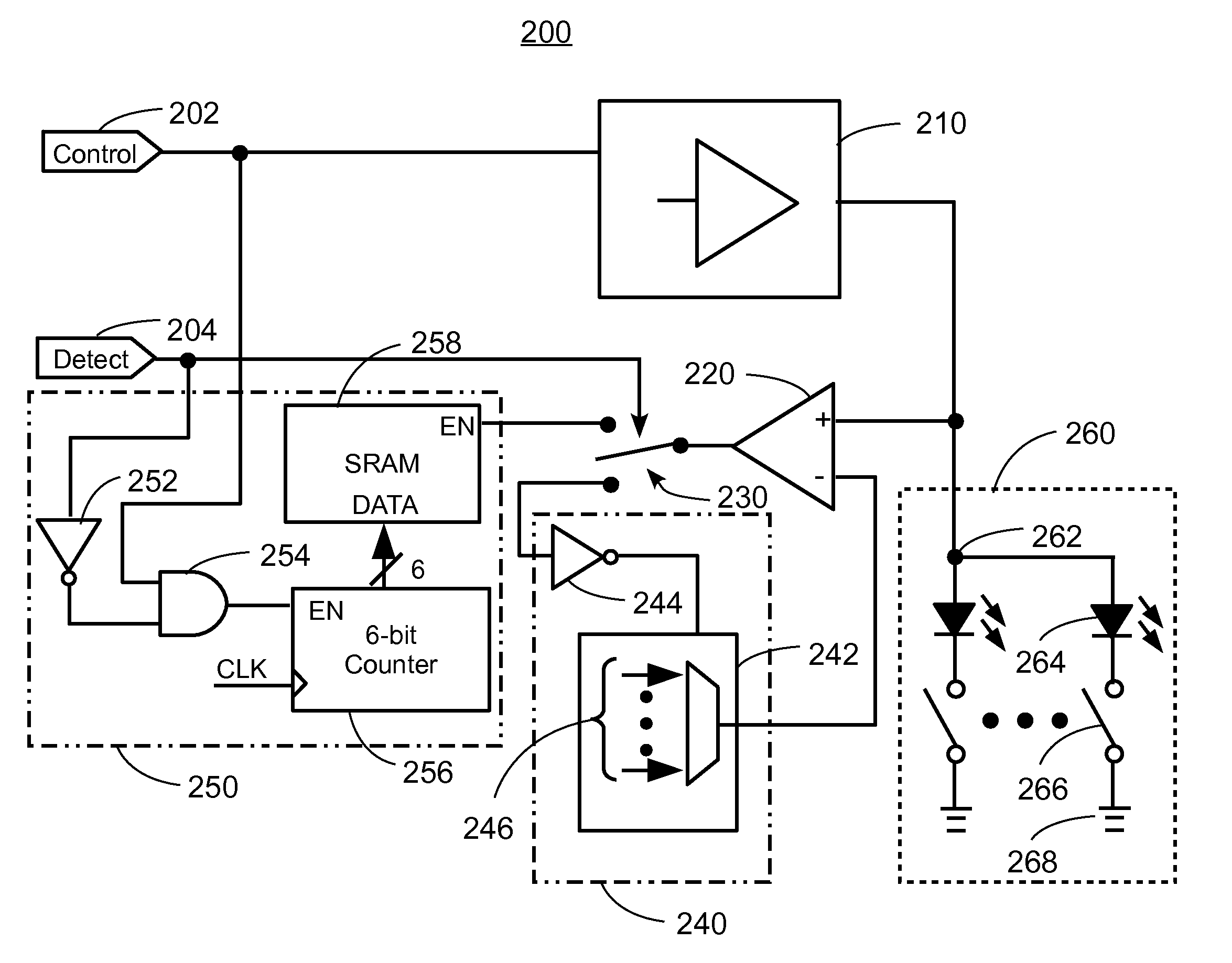
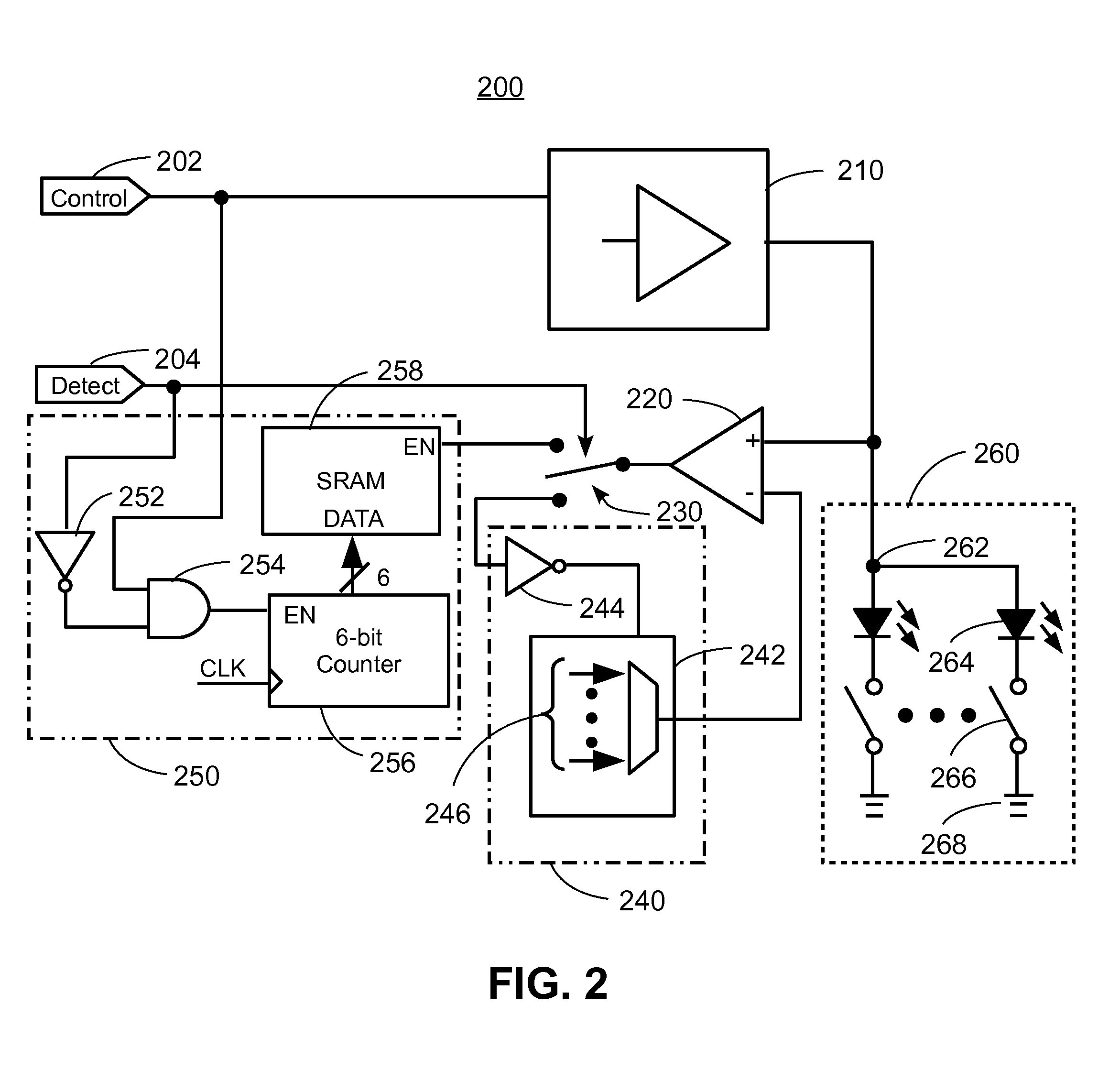
The present invention provides devices and methods for driving LED display panels with equal global charge at minimum gray scale. This is achieved through initializing the LEDs of the display panel and modifying the driving signal based on a compensation parameter determined during the initialization process. The circuits and methods involve detecting the forward voltage of the LEDs and measuring the time it takes for the anode voltage of the LEDs to rise to the detected forward voltage, which is then used to modify the driving signal and ensure consistent lighting of the LEDs. This results in a more efficient and effective driving method for LED display panels.

Problems solved by technology

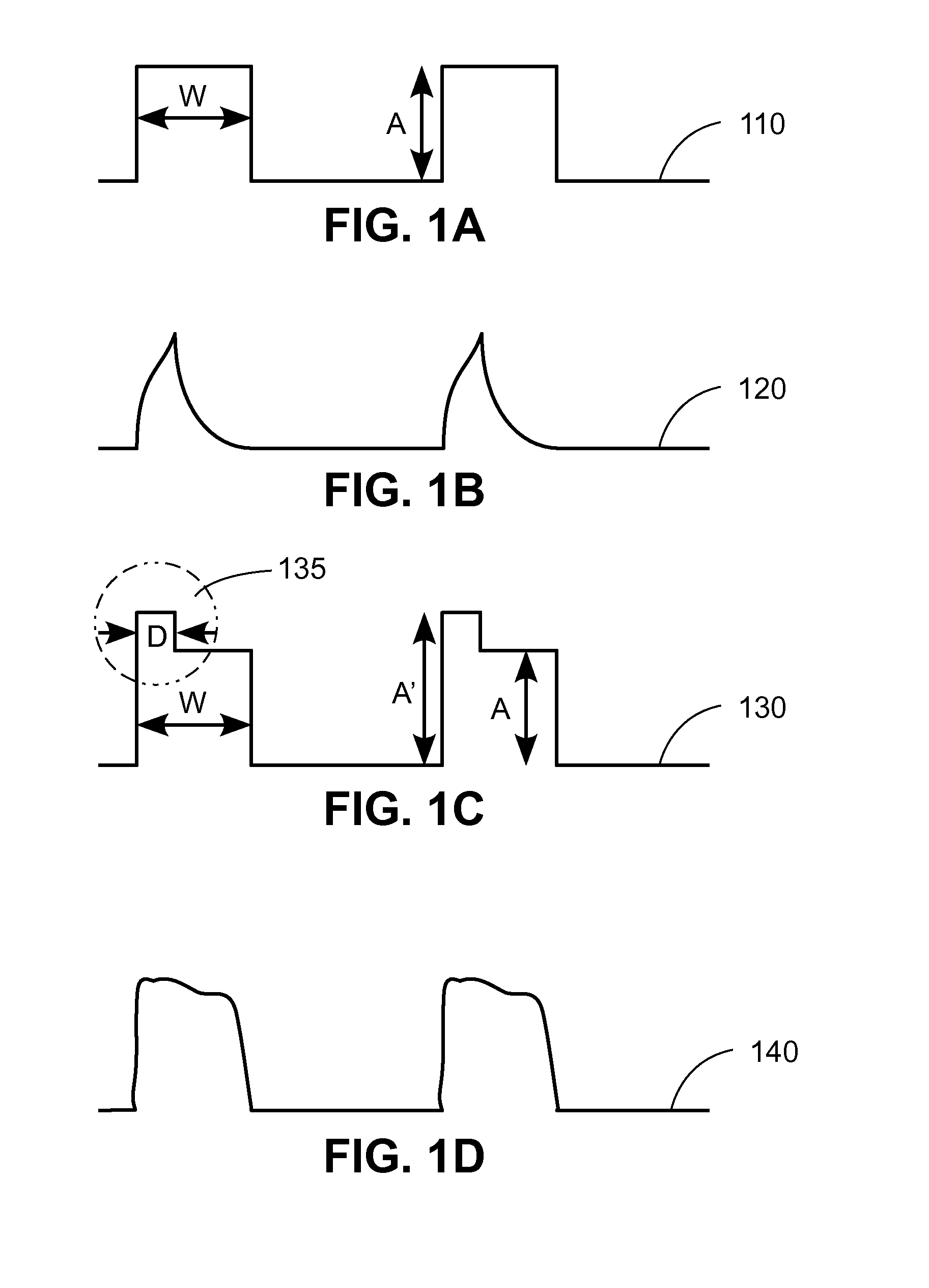
Further, at a low gray scale setting, width W of a PWM signal may be sufficiently narrow, such that the pulses of the PWM signal may be lost due to the uncompensated nature of the driving current and the load characteristics.
Accordingly, even with pre-emphasis, the PWM driving signal may still be distorted, resulting in short pulses and / or accompanying with PWM ringing.

Method used


Image

  • Apparatus and method for driving LED display panel
  • Apparatus and method for driving LED display panel
  • Apparatus and method for driving LED display panel

Examples


Embodiment Construction

[0022]The Figures (FIG.) and the following description relate to the embodiments of the present disclosure by way of illustration only. It should be noted that from the following discussion, alternative embodiments of the structures and / or methods disclosed herein will be readily recognized as viable alternatives that may be employed without departing from the principles of the claimed inventions.

[0023]Reference will now be made in detail to several embodiments of the present disclosure(s), examples of which are illustrated in the accompanying figures. It is noted that wherever practicable similar or like reference numbers may be used in the figures and may indicate similar or like functionality. The figures depict embodiments of the present disclosure for purposes of illustration only. One skilled in the art will readily recognize from the following description that alternative embodiments of the structures and methods illustrated herein may be employed without departing from the p...


PUM


Abstract

The present disclosure provides devices, circuits, and methods for driving an LED display panel, so as to ensure the delivery of equal global charge at minimum gray scale. In one example, the circuit of the present disclosure includes a current source, a detection module, and a measurement module. The current source is configured to generate a current signal for the LEDs. The detection module is configured to detect a forward voltage of the LEDs in response to a low current applied to the LEDs. The detection module is further configured to hold the detected forward voltage. The measurement module is configured to measure a time period for an anode voltage of the LEDs to rise to the detected forward voltage in response to a display current applied to the LEDs.

Description

TECHNICAL FIELD[0001]The present disclosure relates generally to devices, circuits, and methods for driving light emitting diode (LED) display panels. More particularly, the present disclosure relates to devices, circuits, and methods for driving the LED display panels, so as to ensure the delivery of equal global charge at minimum gray scale.BACKGROUND[0002]Recently, light emitting diodes (LEDs) have been widely used in electronic devices and applications. For example, LEDs have been used as light sources for general illumination. Additionally, LEDs have been used to make display panels, televisions, etc. Regardless of the applications, driving circuits are required to supply power to the LEDs and to control the LEDs to illuminate light with the desired brightness.[0003]An LED display panel generally refers to a device which comprises an array of LEDs that are arranged in one or more rows and columns. Alternatively, an LED display panel may include a plurality of sub-modules, each ...

Claims


Application Information

Patent Timeline
IPC IPC(8): H05B33/08H05B44/00
CPCG09G3/32G09G2310/0267G09G2320/064H05B45/20H05B45/397Y02B20/30G09G2310/08
Inventor LI, ERICTANG, SHANG-KUANYANG, WENJIESHEN, LEIZHANG, YICHEN, YUTAONADERSHAHI, NEDI
Owner SCT
Learn More