Tracking algorithm

a tracking algorithm and algorithm technology, applied in the field of tracking, can solve the problems of complex signal variations and simple propagation calculations that are too complex for traditional radio positioning methods to function satisfactorily

Active Publication Date: 2014-05-22
BAE SYSTEMS PLC
View PDF2 Cites 227 Cited by
  • Summary
  • Abstract
  • Description
  • Claims
  • Application Information

AI Technical Summary

Problems solved by technology

However, in complex environments, such as indoors or other cluttered regions, these simple propagation calculations tend to fail.
In cluttered and indoor regions, signal variations tend to be too complex for traditional radio positioning methods to function satisfactorily.

Method used


Image

  • Tracking algorithm
  • Tracking algorithm
  • Tracking algorithm

Examples


Embodiment Construction

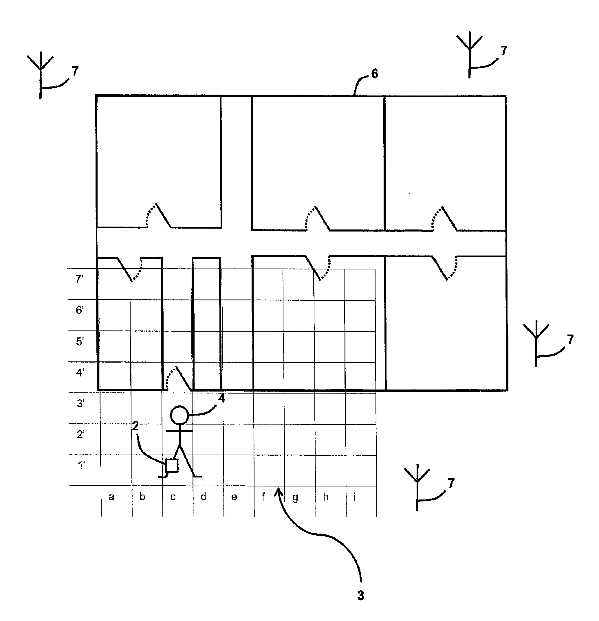
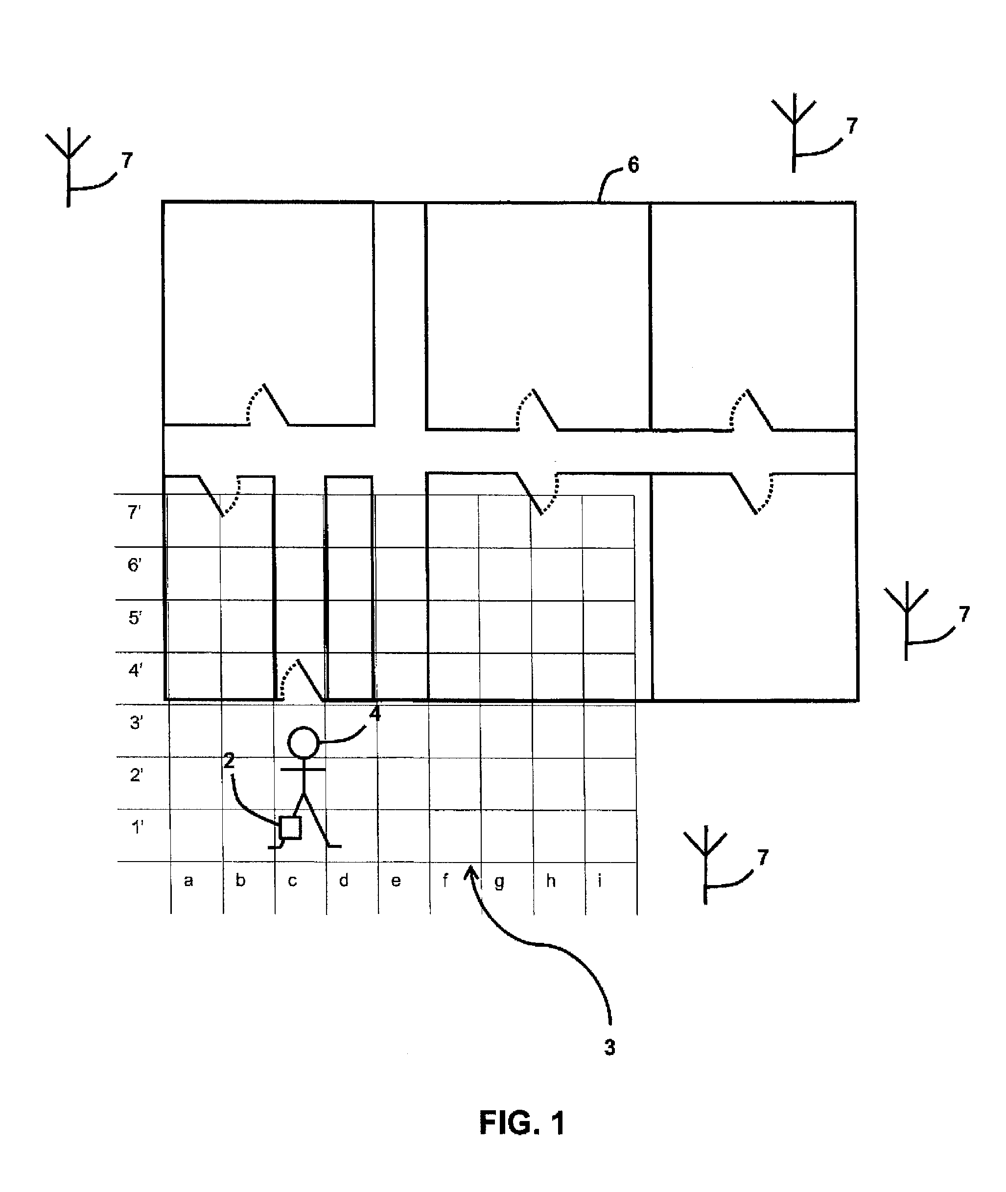
[0037]FIG. 1 is a schematic illustration (not to scale) of a scenario in which an embodiment of a tracking device 2, mounted on a human user 4, is used to generate a radio signal strength map of an area 6.

[0038]The terminology “radio signal strength map of an area” is used herein to refer to a map which provides, for a given point on the map, a magnitude of an electromagnetic field at that point. In this embodiment, a map may be provided in any appropriate way, e.g. pictorially or in data form. A radio signal from which a map is generated may be any appropriate signal or combination of signals, for example, a Wi-Fi™ signal, a Global System for Mobile Communications (GSM) signal, a General Packet Radio Service (GPRS) signal, etc.

[0039]In this scenario, the tracking device 2 is mounted on a shoe of the user 4.

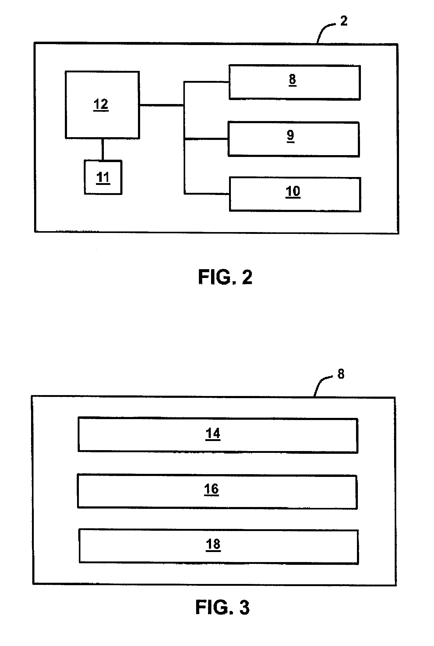
[0040]The tracking device is described in more detail later below with reference to FIG. 2.

[0041]In this scenario, the area 6 is an area inside a building, for example a floor of...


PUM


Abstract

A method of tracking an entity by monitoring a signal, the signal tending to vary spatially and be generally time-invariant, the entity moving from a first location within an area to a second location within the area, the method being suitable for use when the location of the source of the signal is unknown, the method comprising providing a plurality of particles for use with a particle filter, each particle being associated with a first particle location, a first particle location being an estimate of the first location of the entity, providing an estimate of the motion of the entity between the first location and the second location, using the estimate of the motion and using the particle filter, for each particle, updating the first particle location for that particle thereby producing an updated particle location, the updated particle location being an estimate of the second location of the entity, for each updated particle, estimating at least one expected signal parameter at the updated particle location, measuring a signal parameter at the second location of the entity, assigning a weight to each updated particle depending on the expected signal parameter estimated for that particle and the measured signal parameter, estimating the second location of the entity by determining a function of the weighted updated particles, and inputting the estimated location and measured signal parameter, as a location / parameter data set, to a database.

Description

FIELD OF THE INVENTION [0001]The present invention relates to the tracking of an entity within an area.BACKGROUND [0002]An entity may be tracked, i.e. its position at a certain point in time may be estimated or determined, based on an entity's measurement of a given signal metric at locations that the entity visits.[0003]In open outdoor environments, tracking is typically performed by measuring timing or carrier phase measurements. A position of the entity may then be estimated using simple propagation models and databases of transmitter sources.[0004]However, in complex environments, such as indoors or other cluttered regions, these simple propagation calculations tend to fail. Conventional radio positioning methods tend to rely on a radio signal environment being smooth and easily modelled with simple mathematics. In cluttered and indoor regions, signal variations tend to be too complex for traditional radio positioning methods to function satisfactorily.[0005]In a separate field ...

Claims


Application Information

Patent Timeline
Patent Type & Authority Applications(United States)
IPC IPC(8): G01S5/02
CPCG01S5/0278G01S5/02525G01S5/0294
Inventor FARAGHER, RAMSEY MICHAELSARNO, GIUSEPPE CARLOS
Owner BAE SYSTEMS PLC
Why Eureka
Try Eureka