

Isolated power converter, inverting type shunt regulator, and operating method thereof
a technology of inverter type shunt regulator and isolated power converter, which is applied in the direction of electric variable regulation, process and machine control, instruments, etc., can solve the problems of increasing energy consumption, increasing standby power consumption of isolated power converter, and increasing energy consumption, so as to reduce the duty cycle of the switch-driving signal, increase the feedback voltage, and reduce the effect of opto-coupling curren
- Summary
- Abstract
- Description
- Claims
- Application Information
AI Technical Summary
Benefits of technology
Problems solved by technology
Method used
Image

Examples
Embodiment Construction
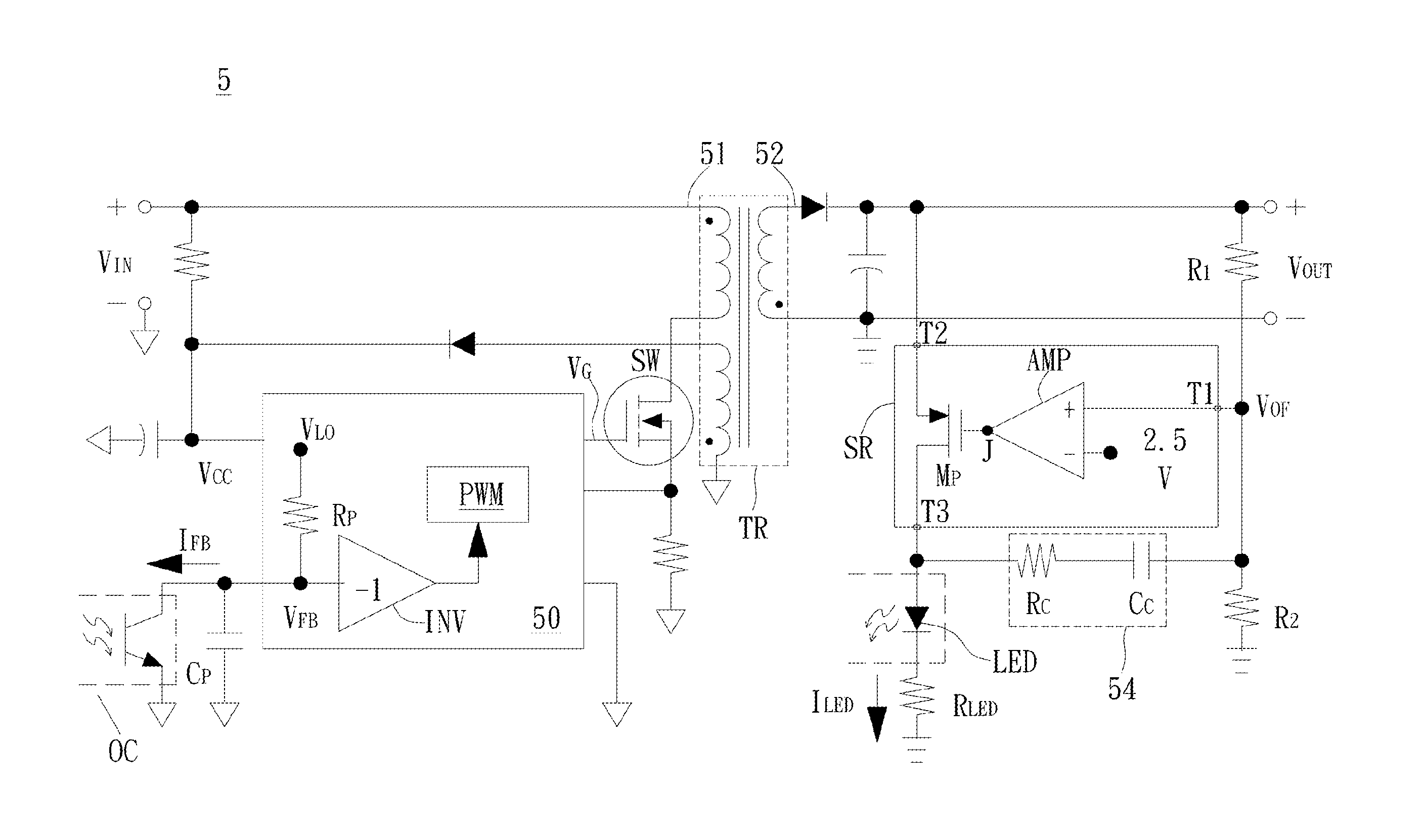
[0037]A preferred embodiment of the invention is an isolated power converter. In fact, the isolated power converter in this embodiment can be, but not limited to, a flyback converter having an isolated transformer. Please refer to FIG. 5A. FIG. 5A illustrates a circuit diagram of a preferred embodiment of the isolated power converter according to the present invention. As shown in FIG. 5A, the isolated power converter 5 includes a primary-side power stage 51, an isolated transformer TR, a secondary-side power stage 52, and a feedback circuit 53. The feedback circuit 53 is implemented with various circuit structures provided by the embodiments of the invention.
[0038]In the embodiment shown in FIG. 5A, the feedback circuit 53 includes a controller 50, an inverting type shunt regulator SR, an optocoupler OC, and a compensating circuit 54. The inverting type shunt regulator SR is used as an error amplifying device in the isolated power converter 5 to replace the conventional three-termi...
PUM
 Abstract
Description
Claims
Application Information