
Coupler for corrugated pipe

a corrugated pipe and coupling technology, applied in the direction of pipe joints, hose connections, fluid pressure sealed joints, etc., can solve the problems of fastening members to be damaged, and corrugated pipes to be damaged

Active Publication Date: 2014-05-29
KOFULSO
View PDF4 Cites 15 Cited by
  • Summary
  • Abstract
  • Description
  • Claims
  • Application Information

AI Technical Summary

Benefits of technology

The present invention is a coupler for corrugated pipes that has a sealing member and a grounding portion to prevent damage to the coupler and to protect the corrugated pipe from lightning. The coupler prevents the fastening force of a cap nut from damaging the fastening member and ensures a proper grounding of the composite member.

Problems solved by technology

When the cap nut is fastened, by the way, the end portion of the corrugated pipe is compressed in the state of being brought into contact with the fastening member, which causes the fastening member to be damaged and accordingly has a bad influence on the sealing state of the corrugated pipe.
Further, in case where the conventional coupler for the corrugated pipe is provided with a composite member having a braided net (steel net) buried into a coated material, as coating means for protecting the corrugated pipe, the lightning transmitted via the braided net of the composite member is not grounded to the outside, which causes the corrugated pipe to be damaged.

Method used


Image

  • Coupler for corrugated pipe
  • Coupler for corrugated pipe
  • Coupler for corrugated pipe

Examples


Embodiment Construction

[0015]Hereinafter, an explanation on a coupler for a corrugated pipe according to a preferred embodiment of the present invention will be in detail given with reference to the attached drawings.

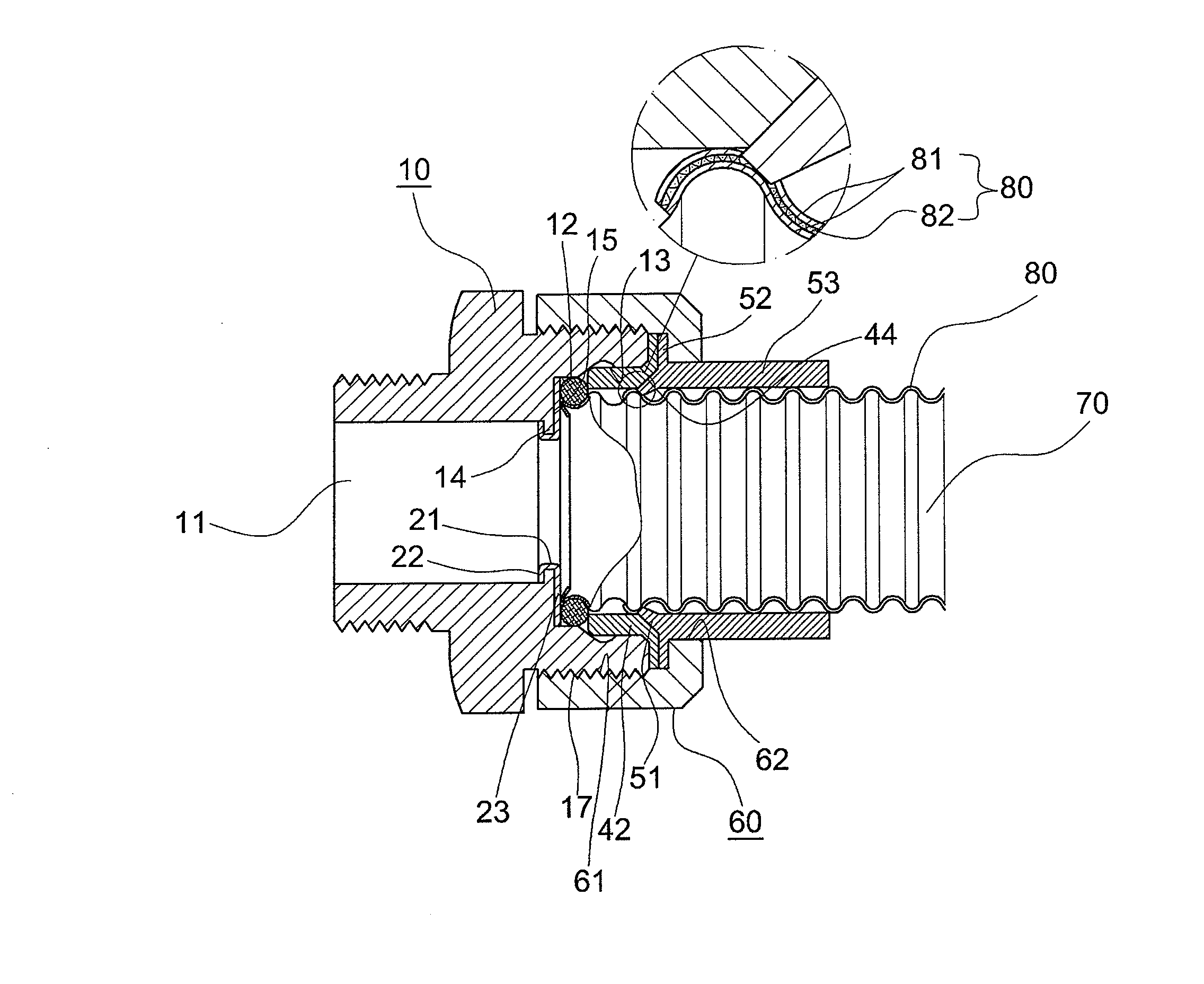
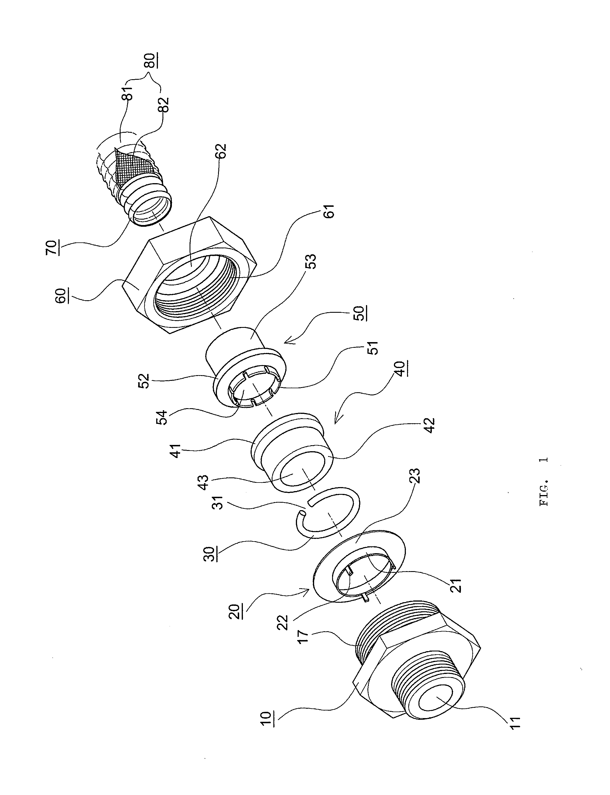
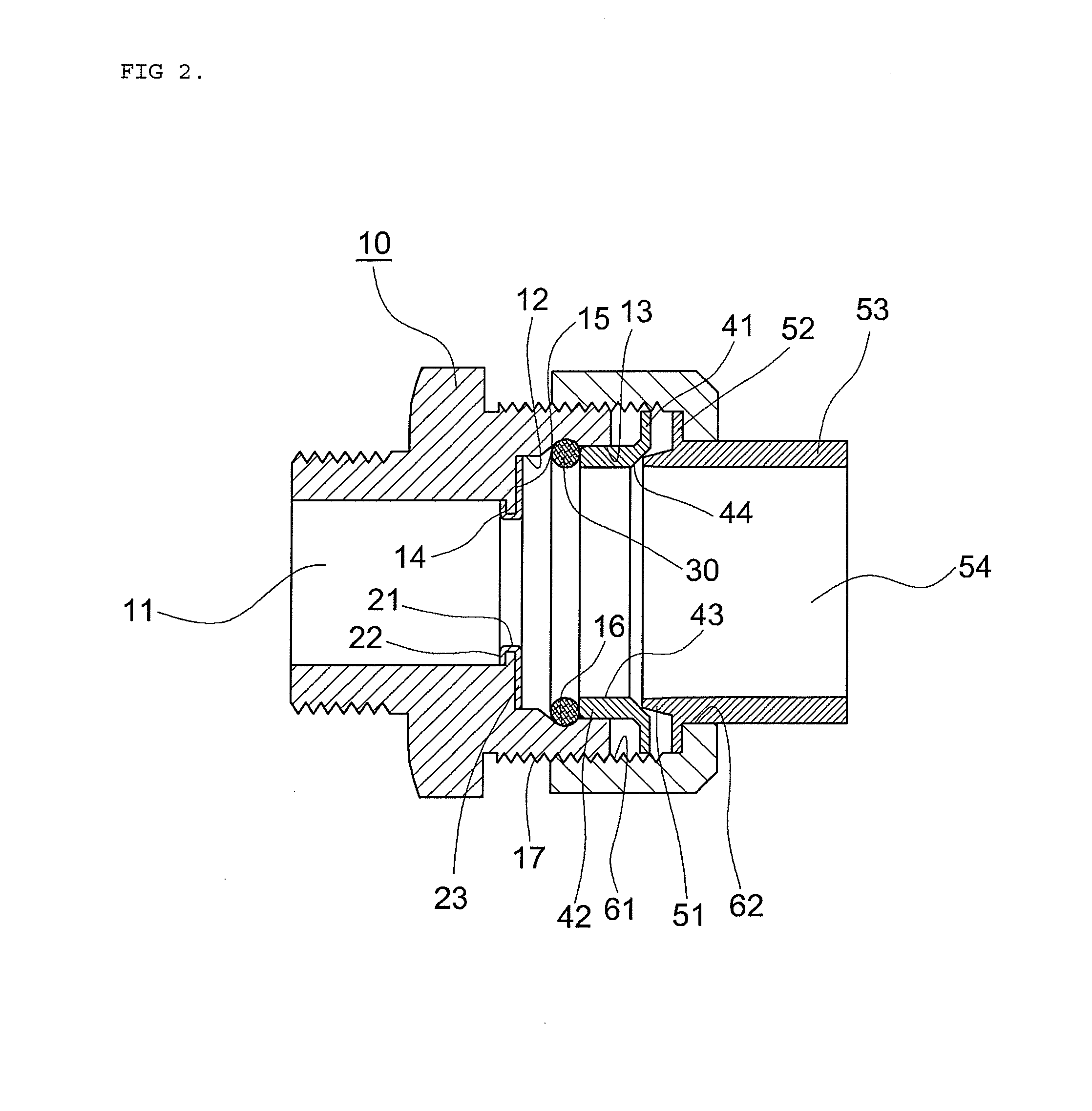
[0016]FIG. 1 is an exploded perspective view showing a coupler for a corrugated pipe according to the present invention, FIG. 2 is a sectional view showing the coupler of the present invention, FIG. 3 is a sectional view showing the coupling of the corrugated pipe to the coupler, and FIGS. 4 and 5 are sectional views showing the coupling and separating states of the corrugated pipe to / from the coupler.

[0017]A corrugated pipe 70, which is used for the coupler of the present invention, is coated with a composite member 80 having a structure wherein a metal braided net 82 is buried into a resin coated layer 81.

[0018]As shown in FIGS. 1 to 5, the coupler for the corrugated pipe according to the present invention largely includes a fastening member 10, a sealing member 20, a compressing member 30,...


PUM


Abstract

The present invention relates to a coupler for a corrugated pipe that is provided with a sealing member mounted inside a fastening member and made of a softer metal material than the corrugated pipe, thereby preventing the fastening member from being damaged due to the fastening force of a cap nut, and that is provided with a grounding portion formed at the front portion of a metal sleeve in such a manner as to enter a coated layer of a composite member and to be grounded to a metal braided net of the composite member when the cap nut is fastened, thereby protecting the corrugated pipe from lightning.

Description

BACKGROUND OF THE INVENTION[0001]1. Field of the Invention[0002]The present invention relates to a coupler for a flexible corrugated pipe having corrugations formed along the outer peripheral surface thereof, and more particularly, to a coupler for a corrugated pipe that is capable of being easily coupled to the corrugated pipe just by fitting the corrugated pipe thereinto and fastening a cap nut to a fastening member.[0003]2. Background of the Related Art[0004]One of conventional couplers for a corrugated pipe is disclosed in U.S. Pat. No. 7,980,601, which is issued to the same applicant as the present invention. According to the conventional coupler, in the state where a cap nut is screw-coupled to a fastening member, the corrugated pipe is pushed through the hole of the cap nut, and next, the cap nut is fastened, so that the corrugations of the corrugated pipe are compressed by means of a compressing member, and thus, the compressing member is moved to a valley portion of the cor...

Claims


Application Information

Patent Timeline
Patent Type & Authority Applications(United States)
IPC IPC(8): F16L25/00
CPCF16L25/0036F16L19/061F16L19/083
Inventor OH, SEUNG-IL
Owner KOFULSO
Learn More