Terminal box

A terminal box and box technology, which is applied to the board/panel/desk of the substation/switchgear, the shell of the substation/distribution device, and the cooling/ventilation of the substation/switchgear, etc. , heat dissipation, etc., to prevent lightning strikes

Inactive Publication Date: 2014-03-26
SHANGQIU POWER SUPPLY CO OF STATE GRID HANAN ELECTRIC POWER CO
View PDF5 Cites 7 Cited by
  • Summary
  • Abstract
  • Description
  • Claims
  • Application Information

AI Technical Summary

Problems solved by technology

The traditional conventional terminal box is just a simple metal shell, which can only provide the most basic physical protection for the electrical components in the box. At the same time, the cover of the terminal box currently used is in the shape of an ordinary canopy. During the maintenance and renovation of the terminal box, the rainwater will flow along the edge of the canopy to the maintenance personnel
The temperature and humidity conditions in the box are greatly affected by the external environment, and the existing terminal boxes are installed outdoors, and the use environment is relatively harsh. Due to the relatively high humidity in the outdoor environment, this will cause Condensed water, which leads to short-circuit failure of electrical components inside the terminal box
At the same time, when the electrical components are working, they will generate a lot of heat. However, in the closed environment of the terminal box, if the heat cannot be dissipated, the internal temperature will be too high, which will cause the electrical components to fail, resulting in failure to work normally.
At the same time, because there are ventilation louver holes on the wall of the cabinet, on the one hand, the temperature and humidity in the cabinet are greatly affected by the environment and cannot be controlled; on the other hand, some insects and small animals will enter the cabinet through the vent holes, affecting the environment. The normal operation of the electrical components in the box will affect the entire circuit system, making it unable to work normally

Method used


Image

  • Terminal box
  • Terminal box

Examples


Embodiment Construction

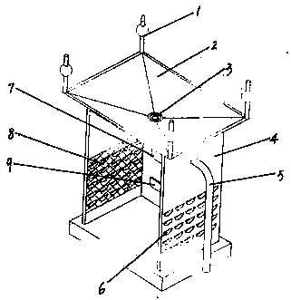
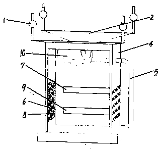
[0010] Embodiments of the present invention will be further described below in conjunction with the accompanying drawings.

[0011] as attached figure 1 , 2 As shown, it includes a box body 4, a cover 2 arranged on the box body 4, a temperature sensor 7 arranged in the box body 4, a humidity sensor 9 arranged in the box body 4, and an air conditioner 10 arranged in the box body 4; The cover 2 is funnel-shaped, with a through hole 3 in the center; the through hole 3 is connected to one end of the discharge pipe 5, and the other end of the discharge pipe 5 is set outside the box body 4; the cover 2 is provided with a lightning rod 1, which can effectively prevent the lightning during the lightning-prone season. Struck by lightning; louvers 6 are set on the side of the box body 4 to dissipate the heat generated in the terminal box; steel wire mesh 8 is set on the inside of the louvers 6, which can effectively prevent insects and small animals from entering the box through the ve...


PUM


Abstract

A terminal box comprises a box body, a cover disposed on the box body, a temperature sensor disposed inside the box body, a humidity sensor disposed inside the box body, and an air conditioner disposed inside the box body. The cover is funnel shaped and provided with a central through hole which is connected with one end of a drain pipe. The other end of the drain pipe is arranged outside the box body. An air conditioner drain pipe is connected with the drain pipe. The box body is provided with the funnel-shaped cover which can effectively collect rainwater, and the rainwater is prevented from flowing to the body of a maintainer; when the interior humidity of the box body measured by the humidity sensor reaches a certain value, the air conditioner inside the box body is capable of automatically removing water to prevent too high interior humidity of the box body from affecting operation of the components inside the box body; when the interior temperature of the box body measured by the temperature sensor reaches a certain value, the air conditioner starts a cooling function and ensures the electric components never fail due to too high temperature; a blind window allows heat generated in the terminal box to dissipate out and also prevents lightning stroke in thundery seasons.

Description

technical field [0001] The invention relates to electric equipment, in particular to a terminal box. Background technique [0002] The terminal box is a kind of electrical equipment box commonly used in substations in the power industry. Traditional conventional terminal boxes were used in the past. The traditional conventional terminal box is just a simple metal shell, which can only provide the most basic physical protection for the electrical components in the box. At the same time, the cover of the terminal box currently used is in the shape of an ordinary canopy. When the terminal box is repaired and rebuilt, rainwater will flow along the edge of the canopy to the maintenance personnel. The temperature and humidity conditions in the box are greatly affected by the external environment, and the existing terminal boxes are installed outdoors, and the use environment is relatively harsh. Due to the relatively high humidity in the outdoor environment, this will cause Cond...

Claims


Application Information

Patent Timeline
Patent Type & Authority Applications(China)
IPC IPC(8): H02B1/28H02B1/56H02B1/04
Inventor 杨素梅戚红向孔祥晨蒋俊杰匡琮姬晓明
Owner SHANGQIU POWER SUPPLY CO OF STATE GRID HANAN ELECTRIC POWER CO
Why Eureka
Try Eureka