
Light source module and display module

a technology of light source module and display module, which is applied in the direction of lighting and heating apparatus, planar/plate-like light guides, instruments, etc., can solve the problems of increased production costs and compromised display quality of lcd apparatus, and achieve the effects of reducing hot spots, increasing yield, and reducing production costs

Active Publication Date: 2014-05-29
AU OPTRONICS CORP
View PDF1 Cites 2 Cited by
  • Summary
  • Abstract
  • Description
  • Claims
  • Application Information

AI Technical Summary

Benefits of technology

The patent text describes a light source module that reduces hot spots during assembly or transport by minimizing collisions and friction caused by the light guide plate. This results in a more favorable display quality and increased yield while decreasing production costs. The technical effect of the patent is to provide a better planar light source and improved display quality.

Problems solved by technology

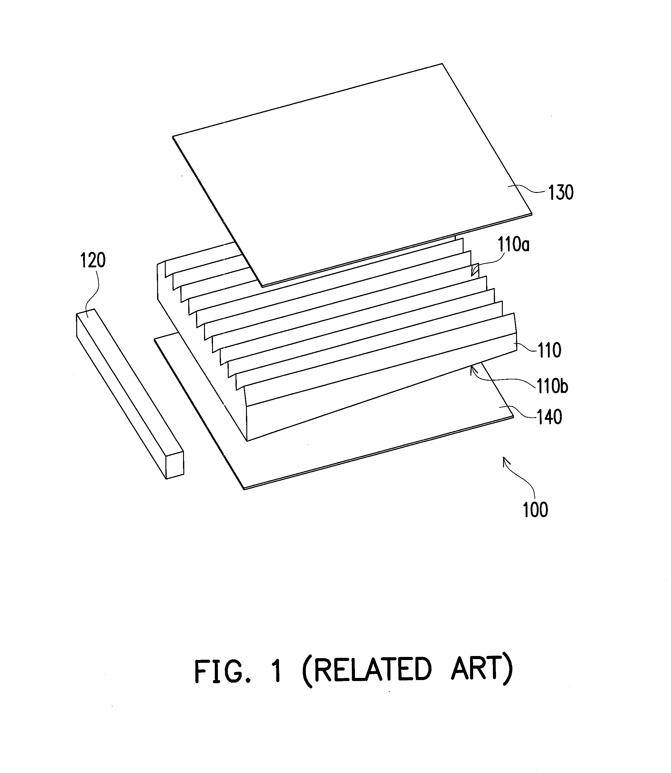
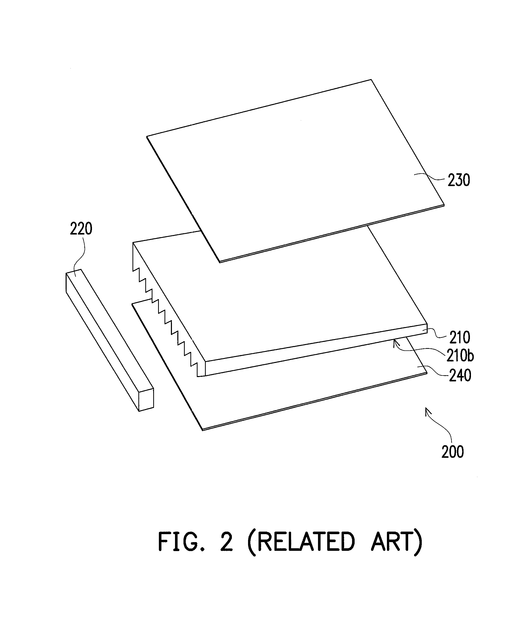
Consequently, not only is the display quality of the LCD apparatus compromised, the production costs are increased because extra optical films are needed to solve the hot spot issue.

Method used


Image

  • Light source module and display module
  • Light source module and display module
  • Light source module and display module

Examples


Embodiment Construction

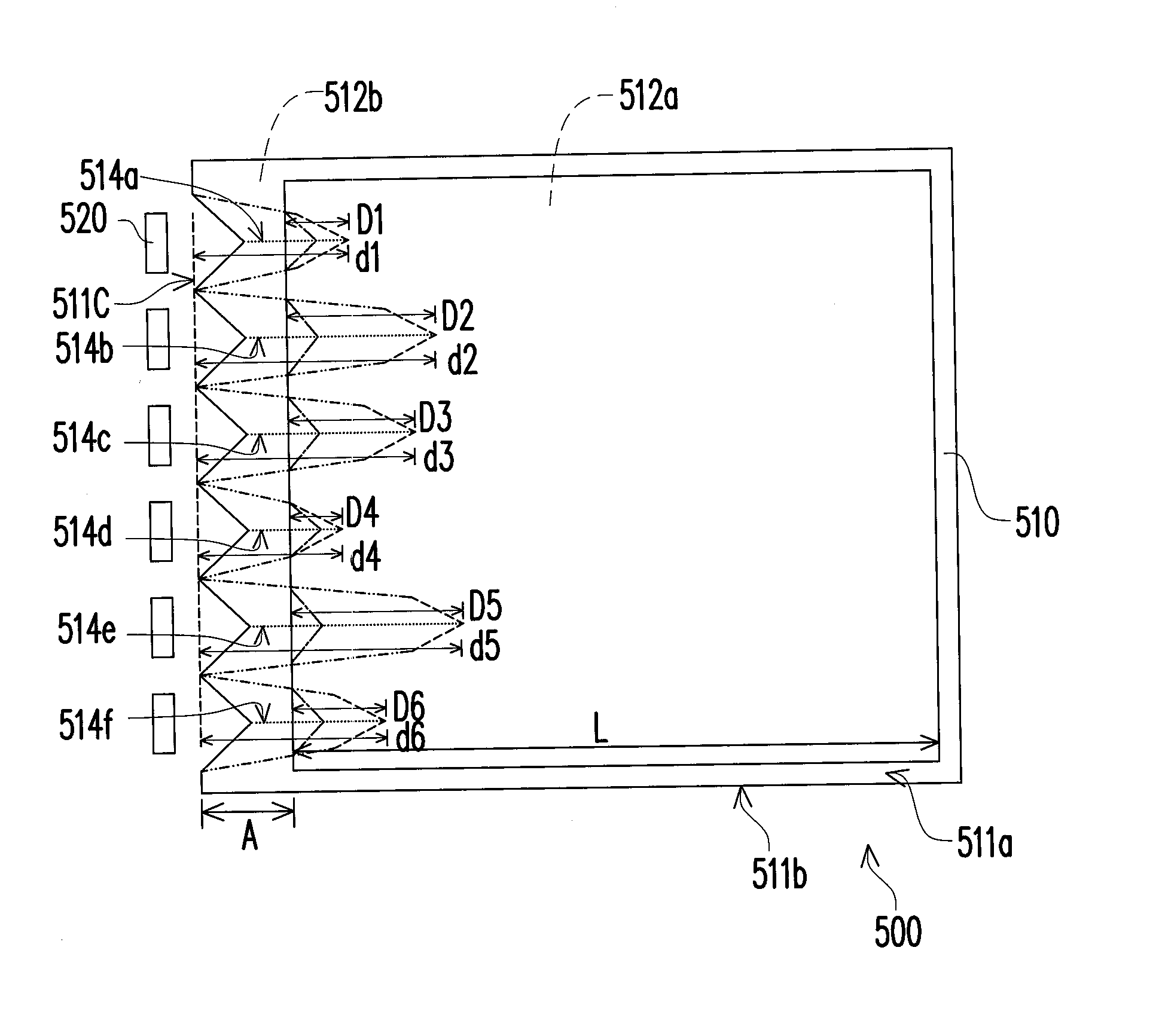
[0034]FIG. 3 represents a schematic diagram illustrating a display module in accordance with one embodiment of the invention. FIG. 4A represents a schematic side views of a backlight module of the display module depicted in FIG. 3. Referring concurrently to FIGS. 3 and 4A, a display module 300 includes a display panel 400 and a light source module 500, in which the light source module 500 is disposed on a side of the display panel 400, for example below the display panel 400. The light source module 500 includes a light guide plate 510 and a light source 520. For example, the light source 520 can be a plurality of point light sources disposed on at least one side of the light guide plate 510, and the point light sources can be formed by a plurality of light emitting diodes (LEDs) for providing light. However, the invention is not limited thereto. In other embodiments of the invention, the light source 520 can be other types of light sources. Typically, light emitted from the light s...


PUM


Abstract

A light source module including a light guide plate and a light source is provided. The light guide plate has a light incident surface and a light emitting region, and the light guide plate has a plurality of grooves or protruding patterns thereon. The length of the grooves or the protruding patterns is smaller than the length of the light guide plate. The light source is disposed on the light incident surface of the light guide plate, and the grooves or the protruding patterns of the light guide plate are disposed beside the light incident surface.

Description

CROSS-REFERENCE TO RELATED APPLICATION[0001]This is a continuation application of and claims the priority benefit of U.S. application Ser. No. 12 / 564,052, filed on Sep. 22, 2009, now pending, which claims the priority benefit of Taiwan application serial no. 98124889, filed on Jul. 23, 2009. The entirety of each of the above-mentioned patent applications is hereby incorporated by reference herein and made a part of this specification.BACKGROUND OF THE INVENTION[0002]1. Field of the Invention[0003]The invention generally relates to a light source module and a display module, and more particularly to a side incident type light source module and a display module having the side incident type light source module.[0004]2. Description of Related Art[0005]The main components of a liquid crystal display (LCD) apparatus includes an LCD panel and a backlight module, in which the LCD panel is formed by two substrates and a liquid crystal layer disposed between the two substrates, and the backl...

Claims


Application Information

Patent Timeline
Patent Type & Authority Applications(United States)
IPC IPC(8): F21V8/00
CPCG02B6/0011G02B6/002G02B6/0038G02B6/0061
Inventor LIAO, SUPER
Owner AU OPTRONICS CORP
Learn More