Object removal detection using 3-d depth information

a technology of depth information and object removal, applied in the field of method and system for detecting object removal from monitored volume, can solve problems such as significant false alarms and process inability to distinguish a pattern chang

Inactive Publication Date: 2014-05-29
PELCO INC
View PDF4 Cites 3 Cited by
  • Summary
  • Abstract
  • Description
  • Claims
  • Application Information

AI Technical Summary

Benefits of technology

[0004]As used herein, the term “rearrangement” means that the volume being monitored, after a detection of movement, retained the content (e.g., an object) at approximately the same depth of field (e.g., the change in the depth of field is within user-specified or automatically determined tolerances). As used herein, the term “...

Problems solved by technology

Object blockage and occlusion is a big challenge in object removal detection, causing significant fal...

Method used


Image

  • Object removal detection using 3-d depth information
  • Object removal detection using 3-d depth information
  • Object removal detection using 3-d depth information

Examples


Embodiment Construction

[0016]A description of example embodiments of the invention follows.

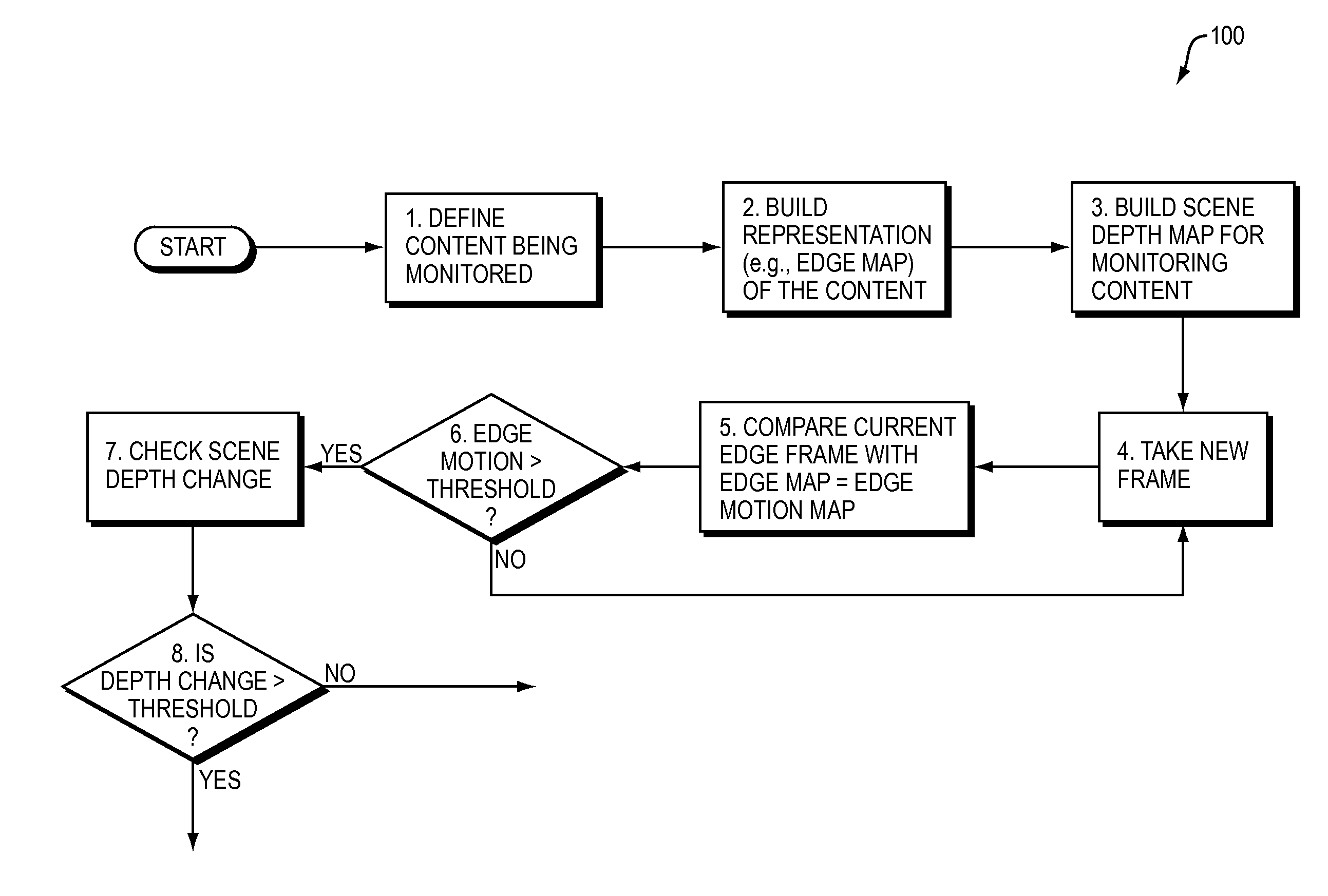
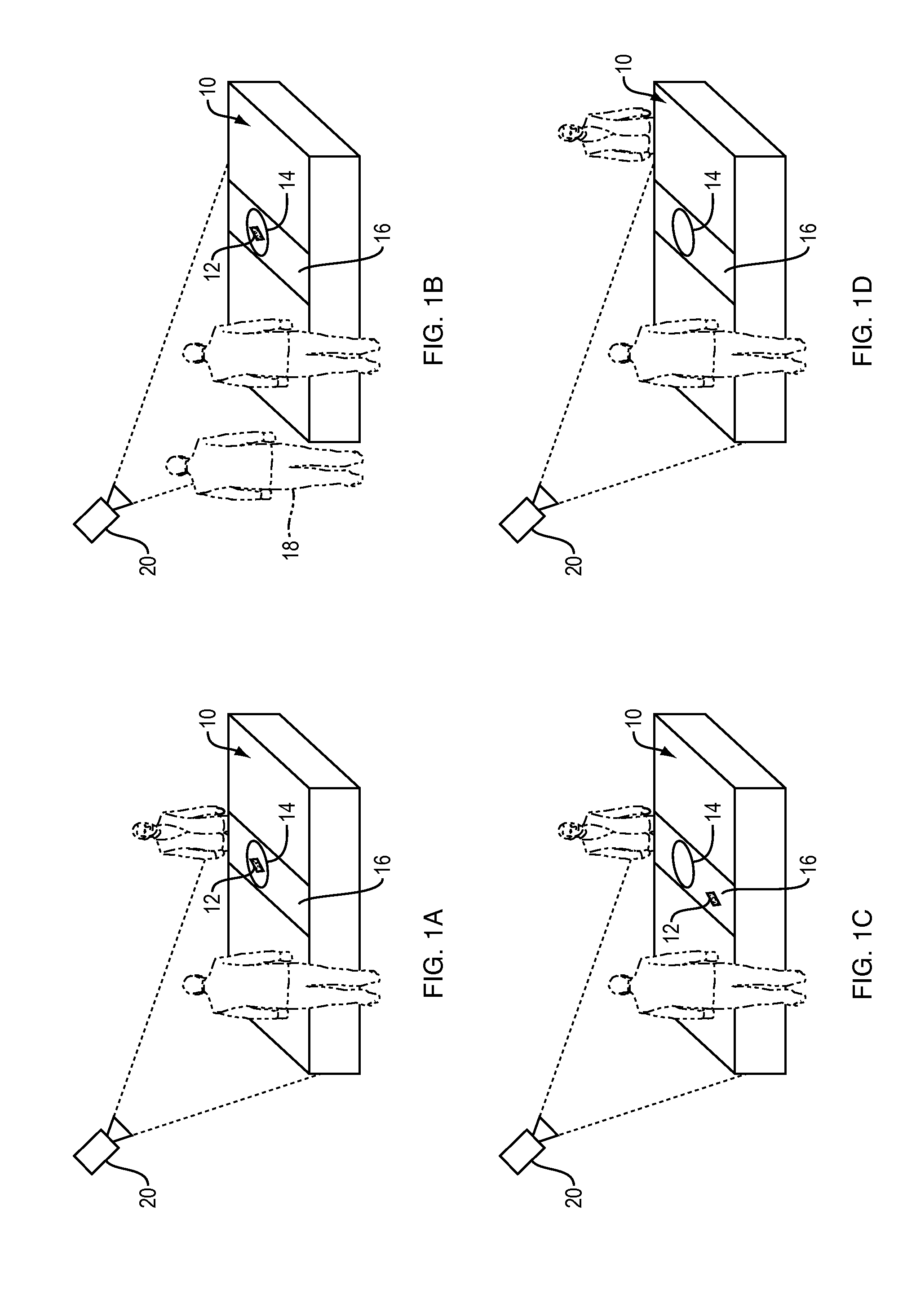
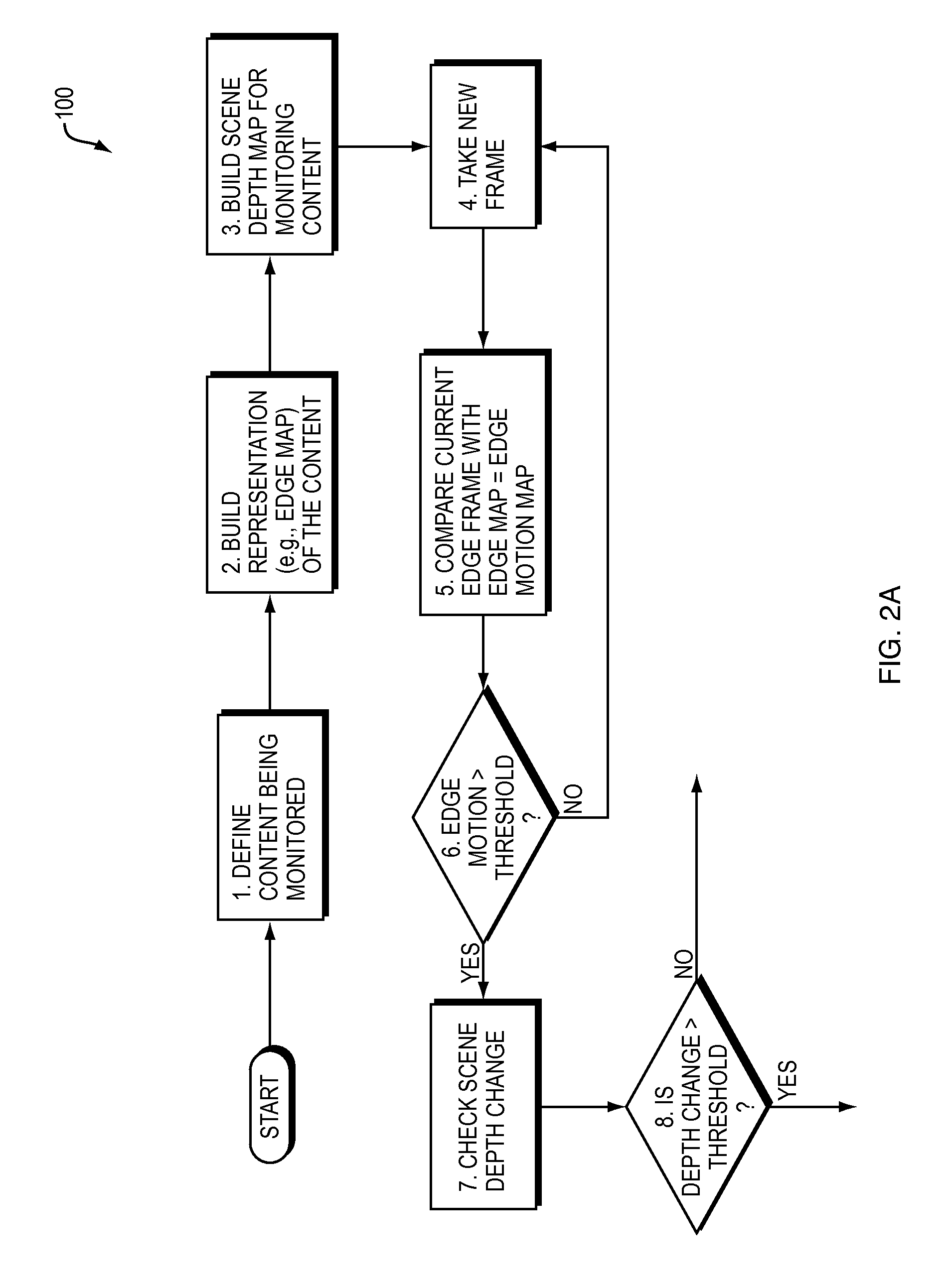
[0017]An embodiment of the present invention may be a method and a system useful for distinguishing object removal from object rearrangement, or from object occlusion by another object. Determining such distinctions can be useful, for example, in reducing false alarms in a case in which a surveillance camera is used to monitor security of an object, such as artwork or jewelry, and report a theft should the object be moved or removed from its expected location. The operation of the method and system of the present invention is illustrated in FIGS. 1A, 1B, 1C, and 1D.

[0018]FIG. 1A shows a monitored volume 10 that includes content (e.g., an object) 12 located within an area 14. In this embodiment, the volume 10 is being monitored by a camera 20. The object 12 is located within a range of depths of field 16 of camera 20.

[0019]FIG. 1B illustrates an occlusion of the content (object) within the monitored volume. Here, ano...


PUM


Abstract

A novel object removal detection method and corresponding apparatus is described. The method employs a combination of detecting a change in a scene pattern and a change in the depth of field. The method significantly reduced false alarms caused by occlusion or rearrangement of the monitored objects.

Description

BACKGROUND OF THE INVENTION[0001]Object blockage and occlusion is a big challenge in object removal detection, causing significant false alarms. In a typical detection process, an image pattern of a protected object is obtained and later compared with the same area pattern in each frame. Any pattern change larger than a threshold produces an object removal alarm. Such a process cannot distinguish a pattern change caused by an object removal or object blockage.SUMMARY OF THE INVENTION[0002]An example embodiment of the present invention is a method and a system for detecting an object removal from a monitored volume.[0003]In one embodiment, the present invention is a method for monitoring a volume. The method comprises constructing a representation of a content in a reference image of a monitored volume to create a reference representation; assigning a reference depth of field value to the reference representation; constructing a representation of a content in a subsequent image of th...

Claims


Application Information

Patent Timeline
IPC IPC(8): G06T7/20
CPCG06T7/2086G08B13/19602G06T2207/10028G06T2207/30232G06T7/254G06T7/285
Inventor YANG, SHU
Owner PELCO INC
Why Eureka
Try Eureka