Gradient index (GRIN) lens chips and associated small form factor optical arrays for optical connections, related fiber optic connectors

a technology of grin lens and small form factor, applied in the field of fiber optic connectors, can solve the problems of additional manufacturing costs, introducing further optical losses, and grin lens may be difficult to precisely position within the ferrule without specialized and expensive equipment, and achieve the effect of efficient alignmen

Active Publication Date: 2014-05-29
CORNING OPTICAL COMM LLC
View PDF10 Cites 40 Cited by
  • Summary
  • Abstract
  • Description
  • Claims
  • Application Information

AI Technical Summary

Benefits of technology

[0012]In this regard in one embodiment, a gradient index (GRIN) lens chip is provided. The GRIN lens chip may include a GRIN lens holder body comprising a fiber mating surface at a fiber end and a terminal mating surface at a terminal end opposite the fiber end. The fiber mating surface may be disposed a longitudinal distance away from the terminal mating surface. The longitudinal distance may be measured parallel to an optical axis. The GRIN lens chip may also include at least one GRIN lens comprising a first end, a second end opposite the first end, a first end face disposed at the f

Problems solved by technology

However, spherical aberrations can occur when the end face of the optical fiber is cleaved and polished into a curved form thereby introducing further optical losses.
However, the GRIN lenses may be challenging to position precisely within the ferrule without specialized and expensive equipment because GRIN lenses may be relatively small, for example, no more than one (1) millimeter in length.
If the GRIN lens is imprecisely positioned within the ferrule, then the ferrule including the GRIN lens may have to be discarded, resulting in additional man

Method used


Image

  • Gradient index (GRIN) lens chips and associated small form factor optical arrays for optical connections, related fiber optic connectors
  • Gradient index (GRIN) lens chips and associated small form factor optical arrays for optical connections, related fiber optic connectors
  • Gradient index (GRIN) lens chips and associated small form factor optical arrays for optical connections, related fiber optic connectors

Examples


Embodiment Construction

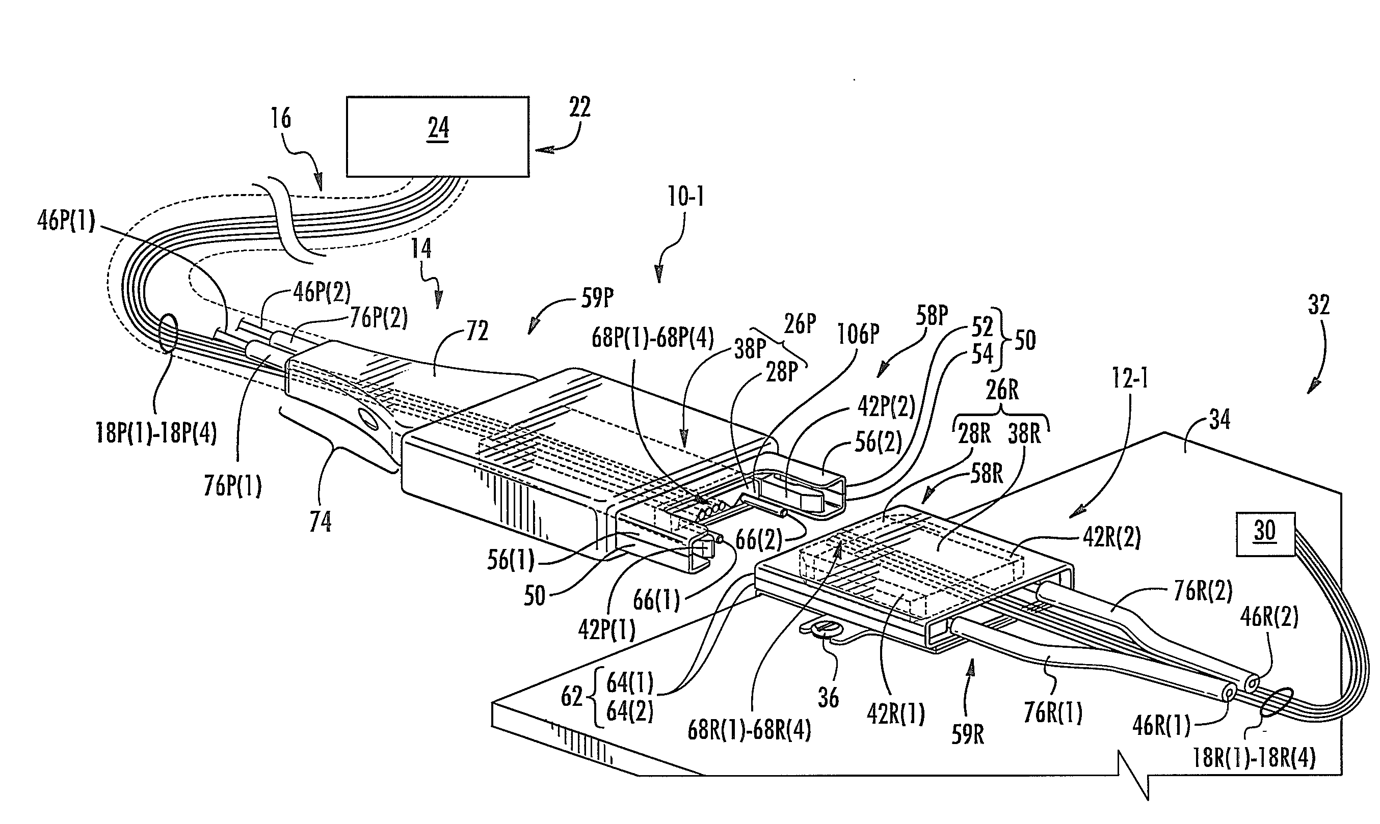
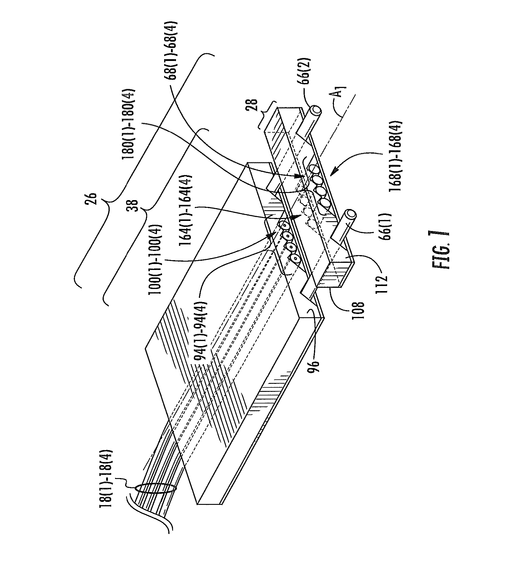
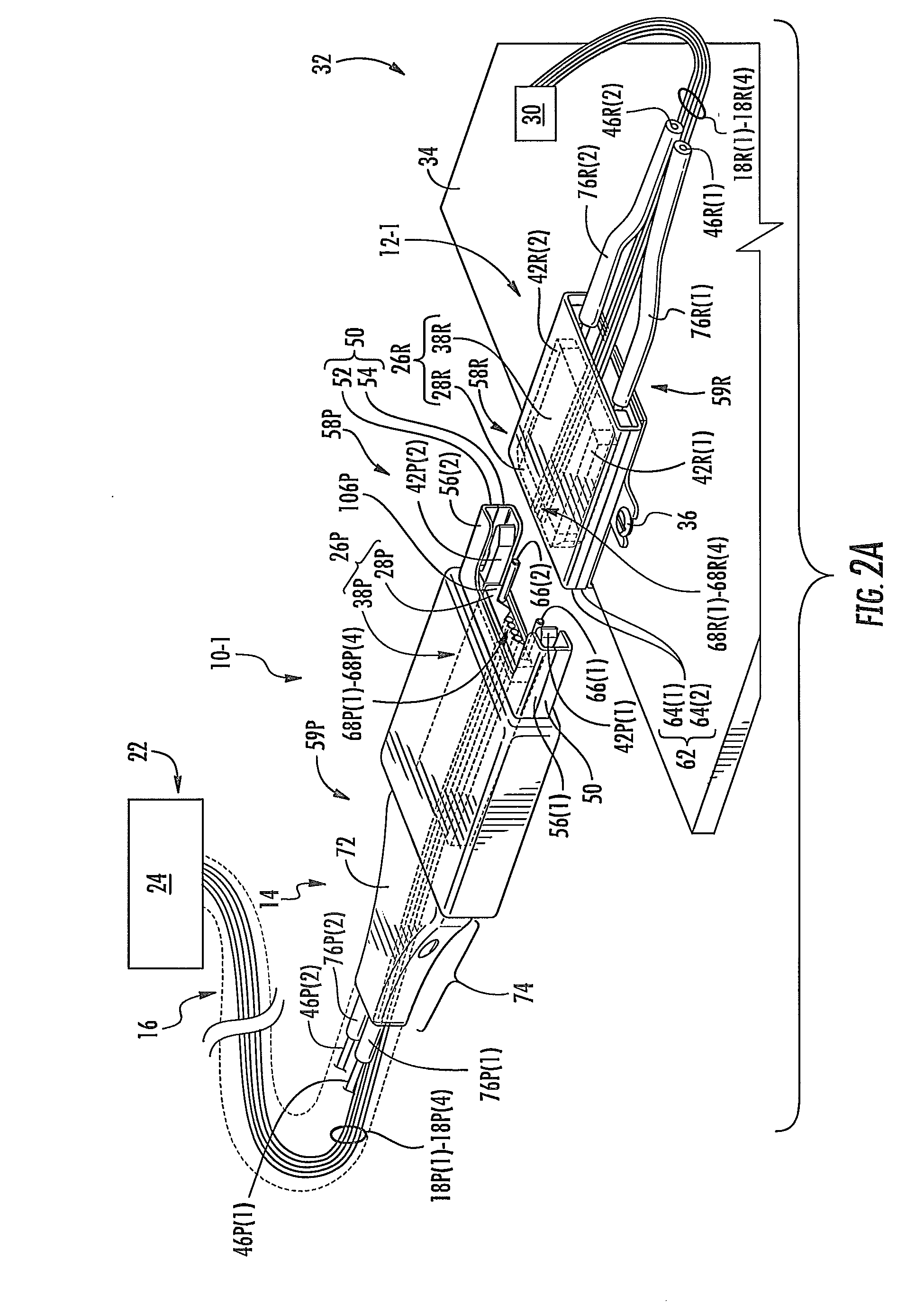
[0011]Embodiments disclosed herein include gradient index (GRIN) lens chips and associated small form factor optical arrays for optical connections, and related fiber optic connectors. By aligning GRIN lenses within a GRIN lens chip, a more precise and reliable alignment may be achieved with respect to optical fibers than if a single conventional ferrule is utilized to align and secure both GRIN lenses and optical fibers. The GRIN lens chip may include a GRIN lens received and thereby aligned within a groove disposed between a fiber end and a terminal end of a GRIN lens holder body. The optical fibers may also be received and thereby aligned within a groove of a ferrule body. In this manner, when the GRIN lens chip containing the GRIN lenses is aligned with a ferrule body containing the optical fibers, then the GRIN lenses may be precisely located relative to the optical fibers.

[0012]In this regard in one embodiment, a gradient index (GRIN) lens chip is provided. The GRIN lens chip ...


PUM


Abstract

Gradient index (GRIN) lens chips and associated small form factor optical arrays for optical connections, and related fiber optic connectors are disclosed. By aligning GRIN lenses within a GRIN lens chip, a more precise and reliable alignment may be achieved with respect to optical fibers than if a single conventional ferrule is utilized to align and secure both GRIN lenses and optical fibers. The GRIN lens chip may include a GRIN lens received and thereby aligned within a groove disposed between a fiber end and a terminal end of a GRIN lens holder body. The optical fibers may also be received and thereby aligned within a groove of a ferrule body. In this manner, when the GRIN lens chip containing the GRIN lenses is aligned with a ferrule body containing the optical fibers, then the GRIN lenses may be precisely located relative to the optical fibers.

Description

BACKGROUND[0001]1. Field of the Disclosure[0002]The technology of the disclosure relates to optical interfaces in fiber optic connector assemblies for establishing fiber optic connections.[0003]2. Technical Background[0004]Benefits of optical fiber include extremely wide bandwidth and low noise operation. Because of these advantages, optical fiber is increasingly being used for a variety of applications, including but not limited to broadband voice, video, and data transmission. Fiber optic networks employing optical fiber are being developed and used to deliver voice, video, and data transmissions to subscribers over both private and public networks. These fiber optic networks often include separated connection points linking optical fibers to provide “live fiber” from one connection point to another connection point. In this regard, fiber optic equipment is located in data distribution centers or central offices to support optical fiber interconnections.[0005]Optical fibers may al...

Claims


Application Information

Patent Timeline
IPC IPC(8): G02B6/36G02B6/32
CPCG02B6/32G02B6/36G02B6/322G02B6/325G02B6/3652G02B6/3807G02B6/3831G02B6/3885G02B6/42
Inventor BHAGAVATULA, VENKATA ADISESHAIAHTREICHLER, GEORGE DAVISVASILAKOS, KEVIN ANDREW
Owner CORNING OPTICAL COMM LLC
Why Eureka
Try Eureka