Vessel bifurcation stent deployment system with zippered catheters

Active Publication Date: 2014-05-29
RUSH UNIV MEDICAL CENT
View PDF9 Cites 67 Cited by
  • Summary
  • Abstract
  • Description
  • Claims
  • Application Information

AI Technical Summary

Benefits of technology

The patent describes a bifurcated catheter system that can deploy a bifurcated stent into a bifurcated vessel. The system includes a y-shaped catheter with a splittable seam and a custom made stent. The stent is preloaded onto a wire which is split into two legs at its distal end. The catheter system allows for easy placement of the stent at the vessel bifurcation, and the stent can be easily deployed and unsheathed to the correct location in the vessel wall. The technical effect of this invention is an effective means for a physician to stent a vessel at a bifurcation of that vessel.

Problems solved by technology

When more than one device is placed with overlap, the risk of complication exponentially increases—vessel wall apposition is decreased and stent material extends into the vessel lumen more than single stent material.
There are several stent designs to overcome the problems associated with a bifurcation, but no current design permits a unitary stent with three tubes to be placed into a bifurcating vessel and, due to the problems described above, such a unitary design is needed.

Method used


Image

  • Vessel bifurcation stent deployment system with zippered catheters
  • Vessel bifurcation stent deployment system with zippered catheters
  • Vessel bifurcation stent deployment system with zippered catheters

Examples


Embodiment Construction

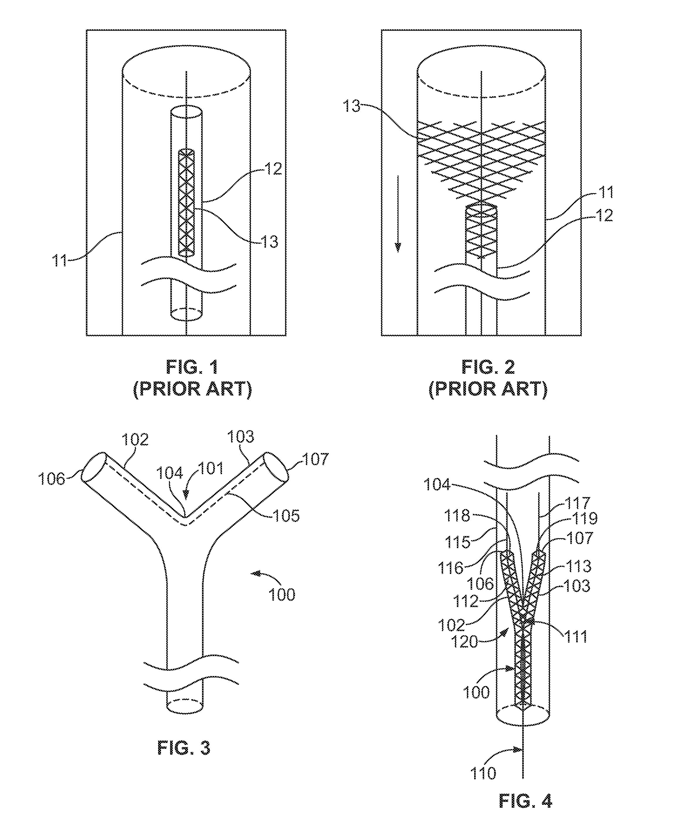
[0047]A known introduction catheter or sheath 11, stent catheter 12 and stent 13 are shown in FIGS. 1-2. The self-expanding stent 13 may deploy automatically upon withdrawal of the catheter 12 as shown in FIG. 2.

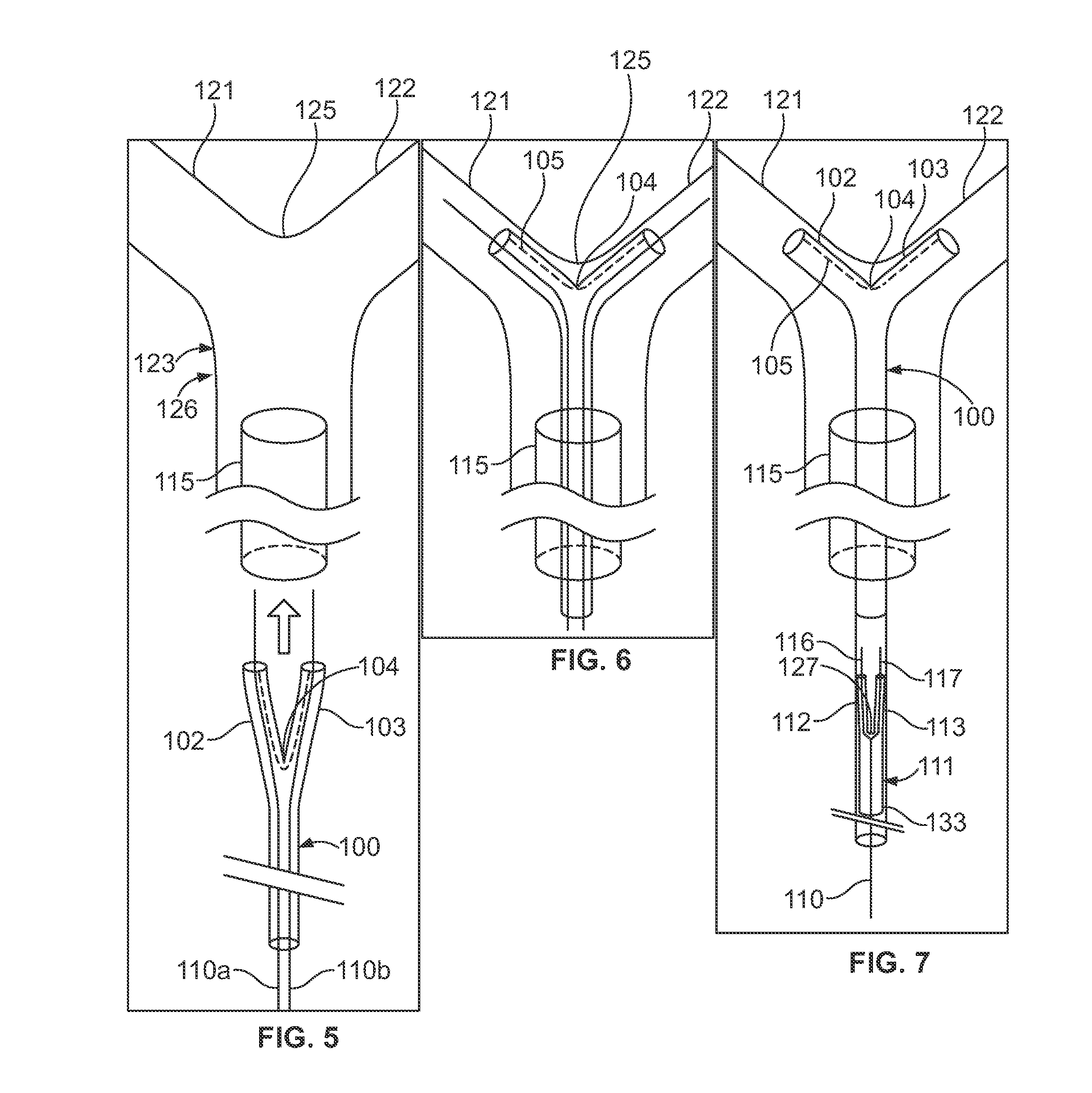
[0048]The disclosed bifurcated stent deployment systems may include two main complements: an electrolytically-dividing bifurcated or y-shaped catheter for deploying a bifurcated or y-shaped guide wire and stent.

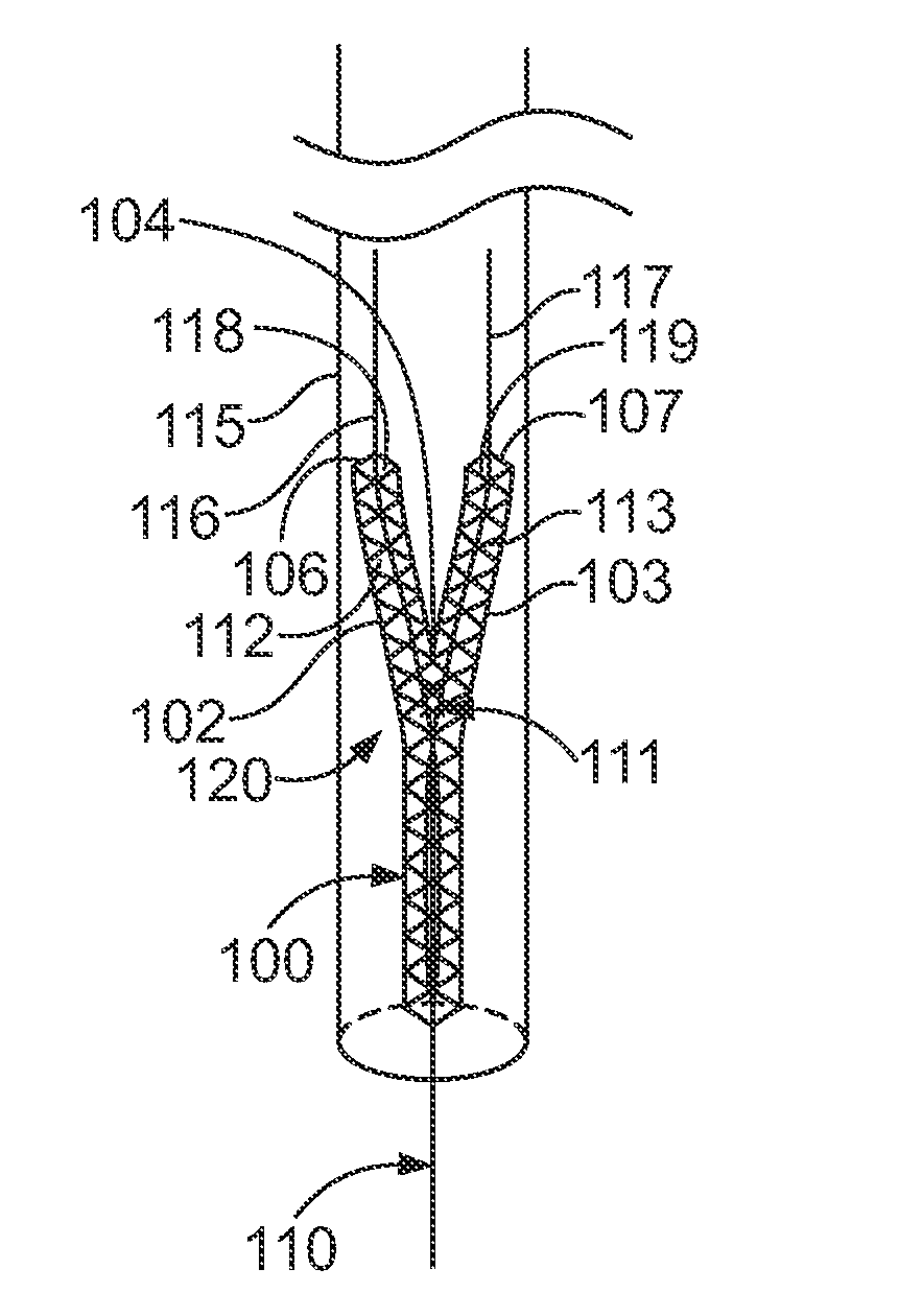
[0049]Turning to FIG. 3, a disclosed bifurcated catheter 100 may fabricated from standard endovascular catheter materials. The distal end 101 may include two branches or legs 102, 103 at its junction 104. Instead of meeting symmetrically at the junction 104, one leg 102, 103 may slightly overlap the other leg 102, 103. The seam 105 that extends along the legs 102, 103 may be connected by filaments (not shown) that detach from each other with the application of electrical current, one or more chemicals or a mechanical force. When using current, the resistance from the ...


PUM


Abstract

A bifurcated catheter, which can deploy a bifurcated stent constructed as a single piece into a bifurcated vessel, is disclosed. The system may have two main parts—a y-shaped catheter with a splittable seam, and a custom made stent, which can be deployed with the bifurcated catheter. The disclosed bifurcated catheter permits a physician or operator to stent a vessel at a bifurcation of the vessel.

Description

BACKGROUND[0001]1. Technical Field[0002]This disclosure relates to medical devices and, more specifically, to medical devices for endovascular deployment in lumens of vasculatures of mammals.[0003]2. Description of the Related Art[0004]It is known that stents can be placed within the vasculature using endovascular techniques for the treatment of diseased vessels. Known applications of stents include treatment of stenotic and atherosclerotic lesions in the coronary, peripheral, and cerebral vasculature. Another common application of stents is the treatment of cerebral aneurysms. Stents are designed to oppose the subject's inner vascular walls and provide an unobstructed conduit for blood flow within the stent lumen.[0005]Stents are generally designed as straight homogenous tubes using biocompatible materials designed to treat the vessel pathology. Placing stents into vessel bifurcations requires deployment of multiple stents given the materials currently available. When more than one...

Claims


Application Information

Patent Timeline
IPC IPC(8): A61F2/954
CPCA61F2/954A61F2/856A61F2/97A61F2002/067A61F2250/0001A61F2250/0071
Inventor JOHNSON, ANDREW K.
Owner RUSH UNIV MEDICAL CENT
Why Eureka
Try Eureka