Exhaust port assembly for a pressure support system

a technology of exhaust gas outlet and pressure support system, which is applied in the direction of breathing protection, instruments, other medical devices, etc., can solve the problems of unresolved problems, noise and direct streaming of exhaust gas flow, and relatively noisy exhaust port, etc., to minimize the area occupied and minimize the noise

Inactive Publication Date: 2005-02-08
RIC INVESTMENTS LLC
View PDF48 Cites 464 Cited by
  • Summary
  • Abstract
  • Description
  • Claims
  • Application Information

AI Technical Summary

Benefits of technology

Accordingly, it is an object of the present invention to provide an exhaust port assembly that overcomes the shortcomings of conventional exhaust vent devices. This object is achieved according to one embodiment of the present invention by providing an exhaust port assembly that includes a conduit having a first end and a second end for carrying a flow of gas and a venting means disposed between the first end and the second end of the conduit. The venting means has a fixed exhaust area for venting a flow of exhaust gas from within the conduit to ambient atmosphere. In addition, the venting means simultaneously minimizes noise associated with the flow of exhaust gas passing to atmosphere, diffuses the flow of exhaust gas passing to ambient atmosphere over a relatively large area, and minimizes the area occupied by the venting means on the conduit.
It is yet another object of the present invention to provide a pressure support system that does not suffer from the disadvantages associated with conventional systems using conventional exhaust port techniques. This object is achieved by providing a pressure support system that includes a pressure generator, a patient circuit, and an exhaust port assembly as described in the immediately preceding two paragraphs.

Problems solved by technology

However, these exhalation ports are relatively noisy due, for example, to the relatively turbulent passage of gas through the holes.
In addition, this exhaust port configuration results in a relatively direct stream of exhaust gas being directed from the mask or patient circuit.
Both noise and direct streaming of the flow of exhaust gas are undesirable, because a typical CPAP system is intended to be used while the patient is asleep.
This exhaust port configuration, however, does not solve the problem of preventing a generally direct or concentrated stream of gas from being directed from the mask onto the user or the user's sleep partner.
However, this exhaust port configuration is very complicated in that the stacked ring configuration is difficult to manufacture and maintain.
Also, the minute exhaust paths defined between each ring are prone to clogging and cleaning is difficult.
This makes the exhaust port assembly bulky and heavy, and it does not minimize the amount of deadspace in the patient circuit.

Method used


Image

  • Exhaust port assembly for a pressure support system
  • Exhaust port assembly for a pressure support system
  • Exhaust port assembly for a pressure support system

Examples


first embodiment

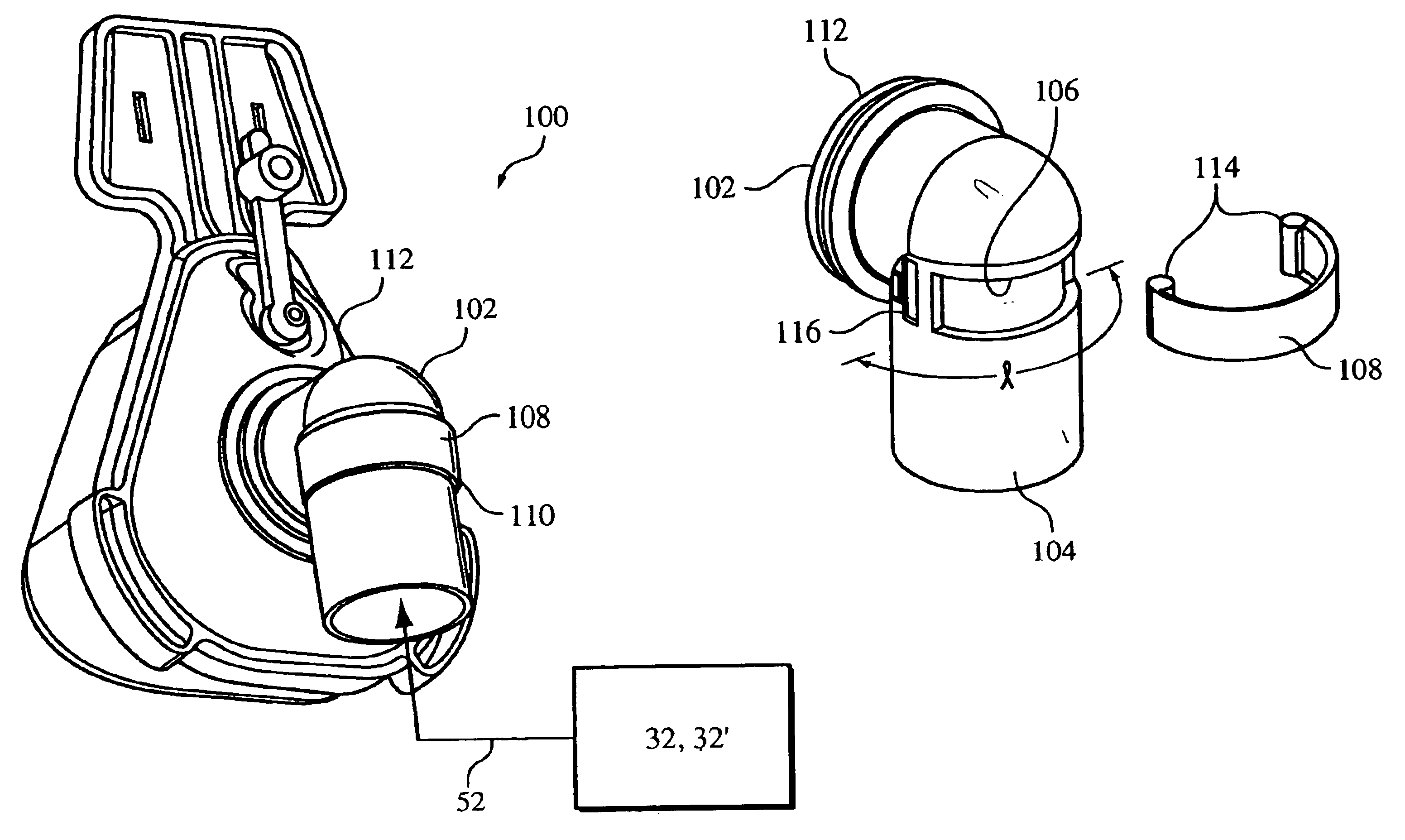
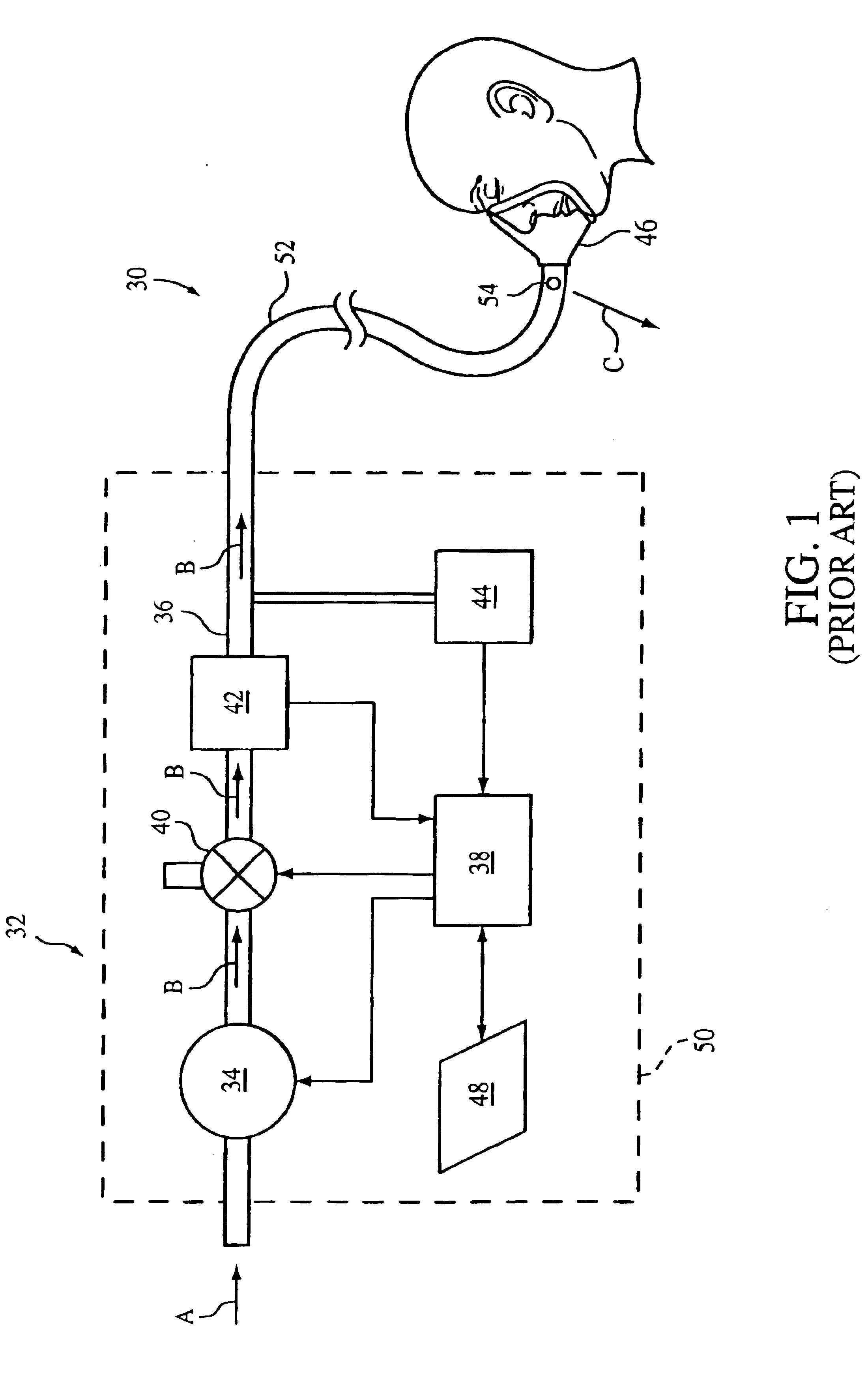
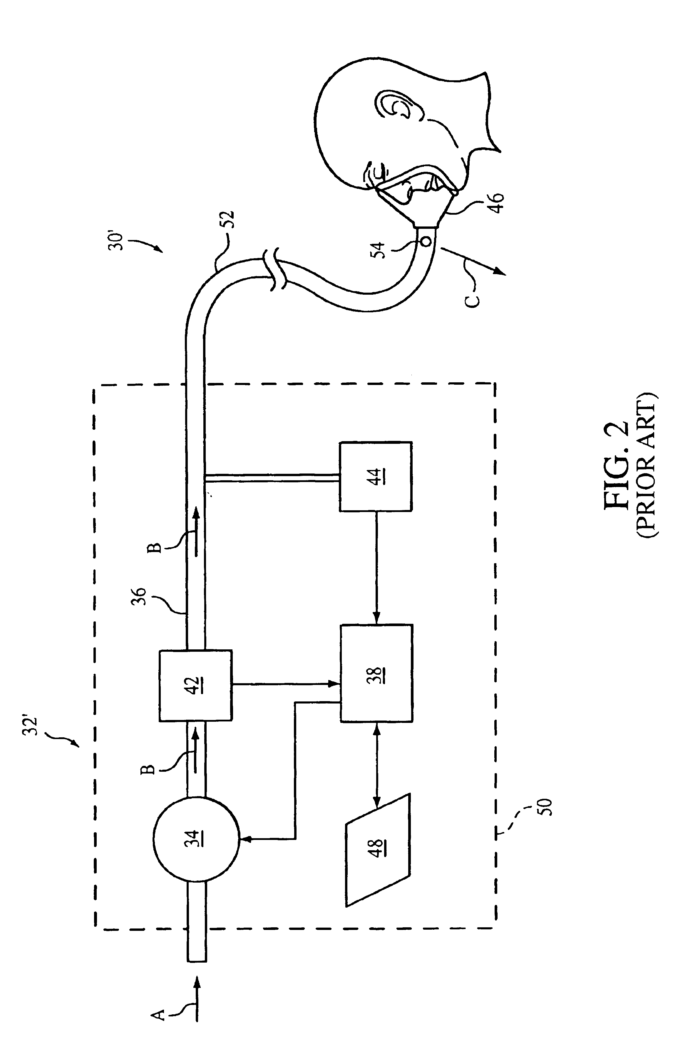
FIG. 3 schematically illustrates a pressure support system 60 according to the principles of the present invention. Pressure support system 60 includes a pressure generating system 32, 32′, a patient interface device 46, a patient circuit 52, and an exhaust port assembly 62. Pressure generating system 32, 32′ corresponds to any conventional pressure generating system, such as those discussed above with respect to FIGS. 1 and 2. Similarly, the present invention contemplates that patient interface device 46 corresponds to any conventional patient interface device. For illustration purposes the patient interface device shown in FIG. 3 is a full face mask that covers the user's nose and mouth.

Exhaust port assembly 62, as shown in greater detail in FIGS. 4-9, includes a vent member 64, a conduit coupling member 66, and a valve member 68. Vent member 64 and conduit coupling member 66 are preferably joined to one another during the manufacturing process using any conventional technique so ...

third embodiment

FIGS. 16, 17, and 18 illustrate an exhaust port assembly 130 according to the principles of the present invention. Exhaust port assembly 130 includes a conduit 132 and a venting structure 134, also referred to as a venting means, for venting a flow of exhaust gas from within the conduit to ambient atmosphere a plurality of holes. As with the embodiment shown in FIGS. 3-9, the venting structure in exhaust port assembly 130 is defined by a plurality of fixed diameter holes 136. These holes are formed through conduit 132 so that a continuous flow of exhaust gas escapes from within the exhaust port assembly to ambient atmosphere. Protrusions 138 are provided among the pattern of holes to prevent the holes from becoming blocked.

The number, size, shape, and spacing of holes 136 are selected as discussed above with respect to the embodiment shown in FIGS. 3-9. However, holes 136 are not formed in a planar surface as in the embodiment shown in FIGS. 3-9. Instead, holes 136 are defined aroun...


PUM


Abstract

An exhaust port assembly comprising a conduit carries a flow of gas. A vent assembly having a fixed exhaust area is provided on the conduit for venting a flow of exhaust gas from within the conduit to ambient atmosphere. The vent assembly is configured so as to minimize noise associated with the flow of exhaust gas passing to atmosphere, diffuse the flow of exhaust gas passing to ambient atmosphere over a relatively large area, and minimize the area occupied by the venting assembly on the conduit.

Description

BACKGROUND OF THE INVENTION1. Field of the InventionThe present invention pertains to an exhaust port assembly for use in a single-limb pressure support system, and, in particular, to an exhaust port assembly with enhanced noise reduction and gas diffusion capabilities, while also minimizing size. The present invention also pertains to a pressure support system using such an exhaust port assembly.2. Description of the Related ArtIt is well known to treat a patient with a non-invasive positive pressure support therapy, in which a flow of breathing gas is delivered to the airway of a patient at a pressure greater than the ambient atmospheric pressure. For example, it is known to use a continuous positive airway pressure (CPAP) device to supply a constant positive pressure to the airway of a patient throughout the patient's respiratory cycle to treat obstructive sleep apnea (OSA), as well as other cardio-pulmonary disorders, such at congestive heart failure (CHF) and cheynes-stokes res...

Claims


Application Information

Patent Timeline
Patent Type & Authority Patents(United States)
IPC IPC(8): A61M16/08A61M16/20A61M16/06A61M16/00
CPCA61M16/08A61M16/208A61M16/06A61M16/0816A61M2230/63A61M2205/42A61M2230/60A61M16/0633
Inventor JAFFRE, MARCEL D.PAUL, ZACHARY D.DUFF, WINSLOW K.BOBECK, MICHAELBUSCH, LANCE
Owner RIC INVESTMENTS LLC
Why Eureka
Try Eureka