Target detecting device for avoiding collision between vehicle and target captured by sensor mounted to the vehicle

a technology of detecting device and target, which is applied in the direction of measuring device, using reradiation, instruments, etc., can solve the problem of weak intensity of reflected waves from pedestrians

Active Publication Date: 2014-06-05
DENSO CORP
View PDF8 Cites 34 Cited by
  • Summary
  • Abstract
  • Description
  • Claims
  • Application Information

AI Technical Summary

Benefits of technology

[0010]The target detecting device comprises a radar sensor, an imaging sensor, and an ECU. The target detected by the radar sensor is selected under certain conditions, for example, i) a reception intensity of the reflected radar waves is equal to or more than a predetermined value, or ii) the target is moving, to be outputted externally.

Problems solved by technology

Therefore, the intensity of reflected waves from the pedestrian is weak.

Method used


Image

  • Target detecting device for avoiding collision between vehicle and target captured by sensor mounted to the vehicle
  • Target detecting device for avoiding collision between vehicle and target captured by sensor mounted to the vehicle
  • Target detecting device for avoiding collision between vehicle and target captured by sensor mounted to the vehicle

Examples


first embodiment

1. Configuration of a Target Detecting Device

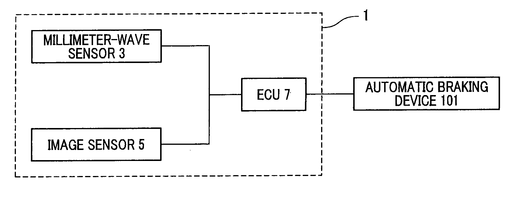
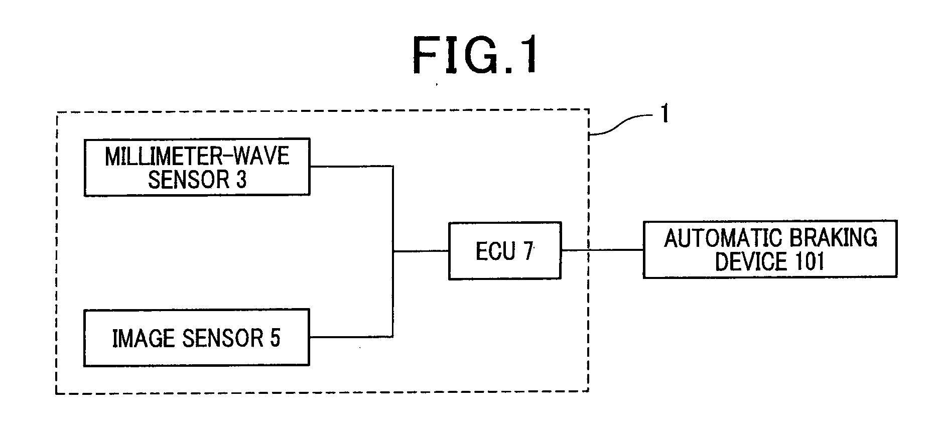
[0026]The first embodiment of the present invention will be described with reference to FIG. 1 to FIG. 4. In FIG. 1, the configuration of the target detecting device is shown. The target detecting device1 is an on-board device that is mounted in a vehicle. The target detecting device 1 detects a target by performing a process described hereafter. The target detecting device 1 then outputs information on the target, such as the type of target, the orientation of the target relative to a reference vehicle, and the distance from the reference vehicle to the target. In the present application, the vehicle in which the target detecting device 1 is mounted is referred to as a “reference vehicle”.

[0027]The target detecting device 1 includes a millimeter-wave sensor 3, an image sensor 5, and an electronic control unit (ECU) 7. The millimeter-wave sensor 3 is configured as a so-called “millimeter-wave radar” to which a frequency modulated continuo...

second embodiment

1. Configuration of a Target Detecting Device

[0056]The configuration (hardware) of a target detecting device according to the second embodiment is basically the same as that of the target detecting device 1 according to the first embodiment. Differences will be described hereafter.

[0057]The target detecting device 1 according to the second embodiment includes the ECU 7. In a manner similar to that according to the first embodiment, the ECU 7 holds, in advance, patterns for image recognition. The patterns correspond with numerous types of targets, such as vehicles, the entire body of a pedestrian, and the upper body of a pedestrian. The ECU 7 selects 100 patterns from the patterns that are being held. The ECU 7 then performs image recognition by comparing each of the 100 patterns with the image acquired by the image sensor 5. Among the 100 patterns, the number P of patterns of the upper body of a pedestrian is normally 10. However, as described hereafter, the number P of patterns of ...

third embodiment

[0084]The configuration of the target detecting device 1 and the process performed by the target detecting device 1 according to a third embodiment are basically similar to those according to the second embodiment. However, there are partial differences. The difference will mainly be described hereafter. The target detecting device 1 according to the third embodiment performs a process shown in the flowchart in FIG. 6. The process differs from that according to the second embodiment in that the above-described processing operation at Step 55 is not included. The processing operations at Step 101 to Step 111 correspond with Step 51 to Step 54 and Step 56 to Step 62 according to the second embodiment.

[0085]In other words, according to the third embodiment, the value of N remains set to the normal value (3) even for image recognition of the area A1. The area A1 is an area in the image acquired by the image sensor 5 that overlaps with the stopped vehicle 105. The target detecting device...


PUM


Abstract

The target detecting device comprises a radar sensor, an imaging sensor, and an ECU. The target detected by the radar sensor is selected under certain conditions, for example, i) a reception intensity of the reflected radar waves is equal to or more than a predetermined value, or ii) the target is moving, to be outputted externally. When a stopped vehicle is detected on a road by the sensor, and a target, for example a pedestrian, present behind the stopped vehicle is detected from the image acquired by the imaging sensor by performing image recognition using predetermined patterns of a target, the ECU makes the selection condition less restrictive than the selection condition for targets other than the target present behind the stopped vehicle, or unconditionally selects the target present behind the stopped vehicle.

Description

CROSS-REFERENCE TO RELATED APPLICATION[0001]This application is based on and claims the benefit of priority from earlier Japanese Patent Applications No. 2012-264509 and No. 2012-264510 respectively filed Dec. 3, 2012, the descriptions of which are incorporated herein by reference.BACKGROUND[0002]1. Field of the Invention[0003]The present invention relates to a target detecting device for avoiding a collision between a vehicle and a target, such as a pedestrian, captured by a sensor mounted to the vehicle.[0004]2. Description of the Related Art[0005]Conventionally, a technology is known in which targets, such as pedestrians and vehicles, present near a reference vehicle are detected using a millimeter-wave sensor. Among the detected targets, a target that satisfies a predetermined condition, such as the intensity of reflected waves from the target being a predetermined value or more, is selected. Information on the selected target is then outputted. The outputted target information ...

Claims


Application Information

Patent Timeline
Patent Type & Authority Applications(United States)
IPC IPC(8): G01S13/93G01S13/931
CPCG01S13/867G01S13/931G01S7/03G01S13/93G01S2013/9323G01S2013/93185
Inventor BABA, TAKAHIRO
Owner DENSO CORP
Why Eureka
Try Eureka