Zoom lens and electronic device including the same

a technology of electronic devices and zoom lenses, applied in the direction of color television details, instruments, television systems, etc., can solve the problem of not being able to ensure the performance of the zoom lens

Active Publication Date: 2014-06-05
SAMSUNG ELECTRONICS CO LTD
View PDF9 Cites 11 Cited by
  • Summary
  • Abstract
  • Description
  • Claims
  • Application Information

AI Technical Summary

Benefits of technology

[0010]One or more embodiments include a zoom lens having a function to correct blur in a captured image due to vibration, and an imaging device including the zoom lens.

Problems solved by technology

However, in Japanese Patent Publication No. 2012-047813, a second lens group and a third lens group are positioned too far away from each other at a telephoto end.
However, in a configuration of Japanese Patent Publication No. 2012-047813, since the second lens group and the third lens group are positioned too far away from each other at the telephoto end, as described above, a configuration in which the VCM is inserted into the unit including the second lens group and the third lens group may not be employed.
In addition, in Japanese Patent Publication No. 2012-047813, a fourth lens group includes one lens, but it is not likely to ensure a performance of the zoom lens if a final lens group (lens group closest to the image side) is made up of only one lens.

Method used


Image

  • Zoom lens and electronic device including the same
  • Zoom lens and electronic device including the same
  • Zoom lens and electronic device including the same

Examples


embodiment 1

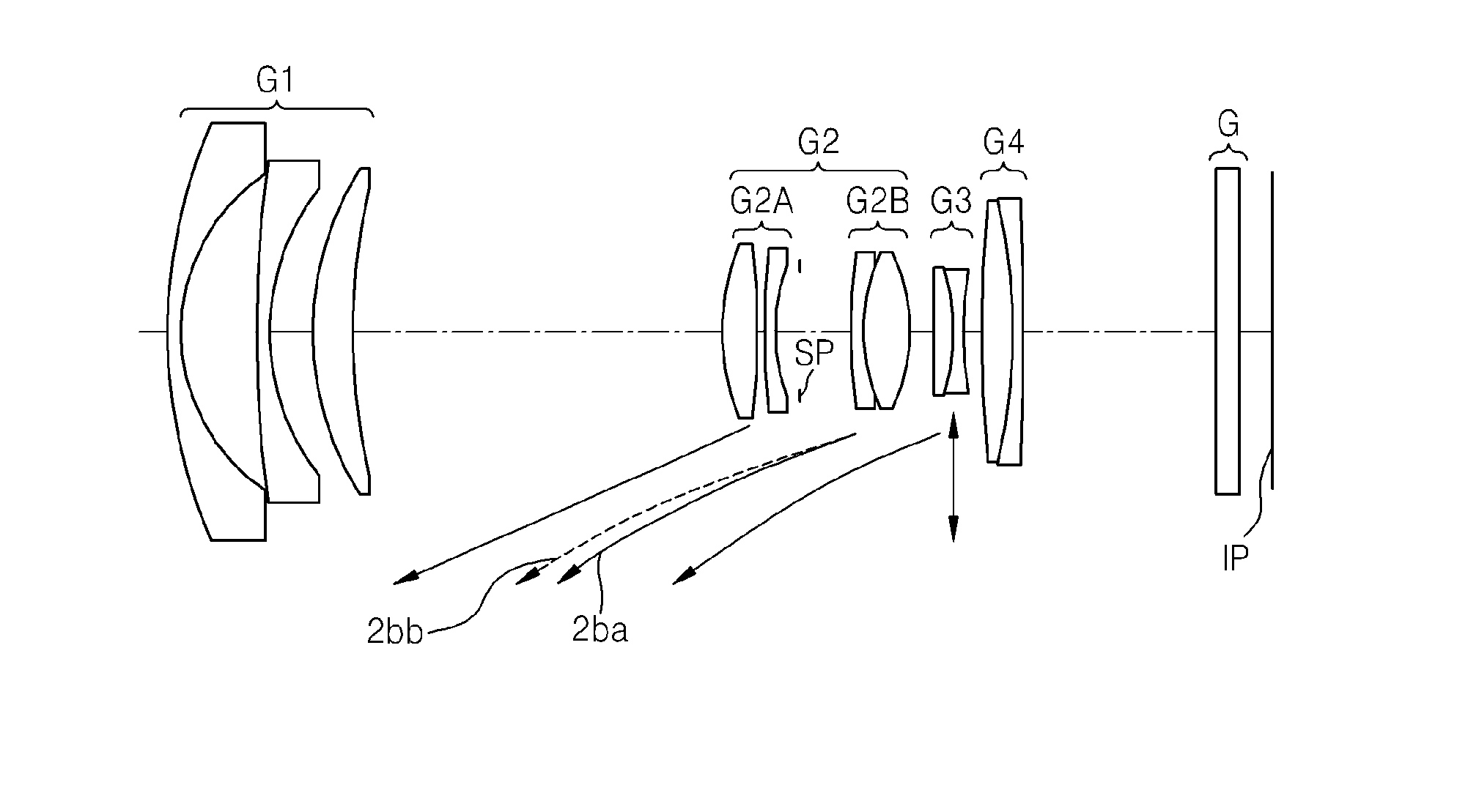
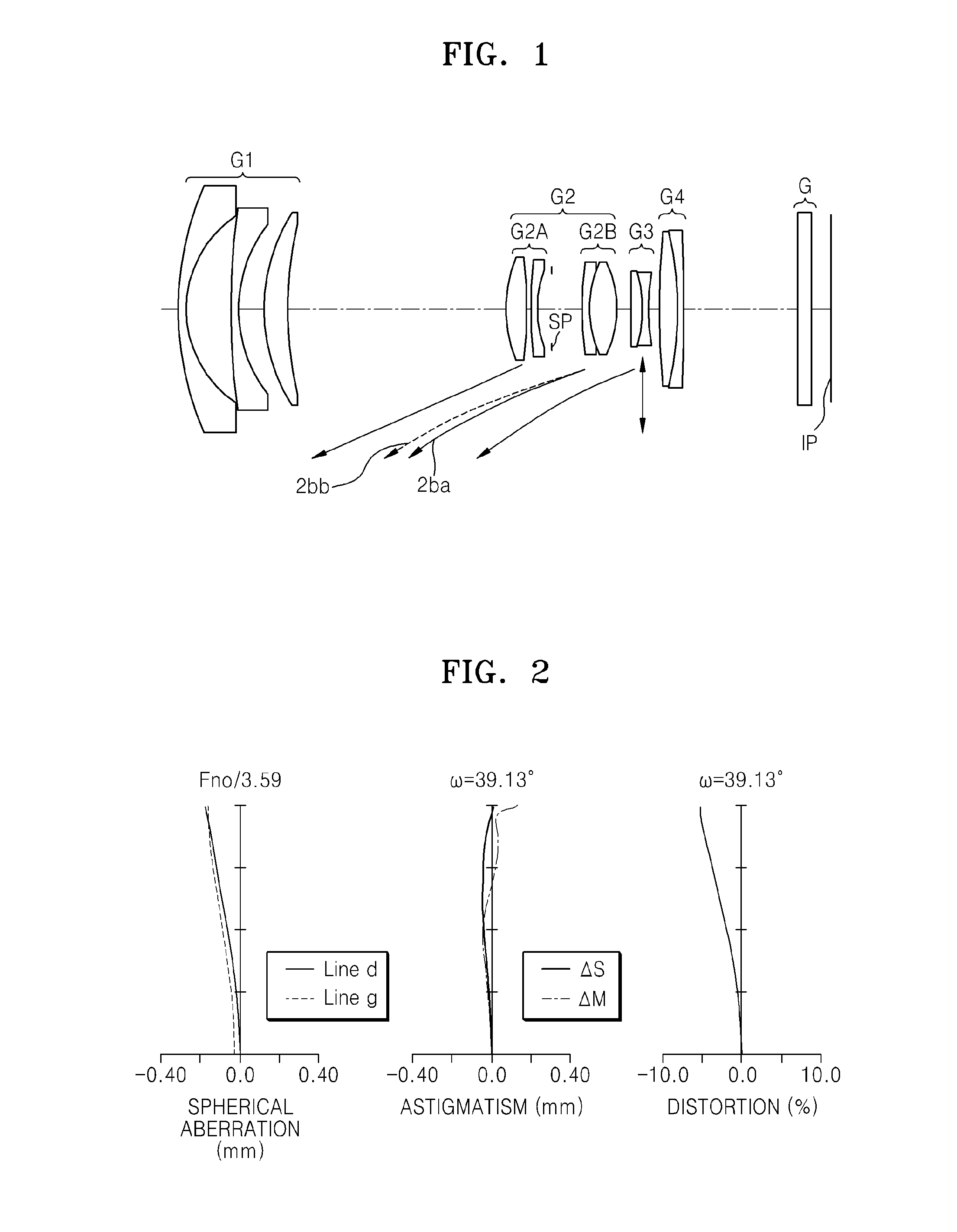
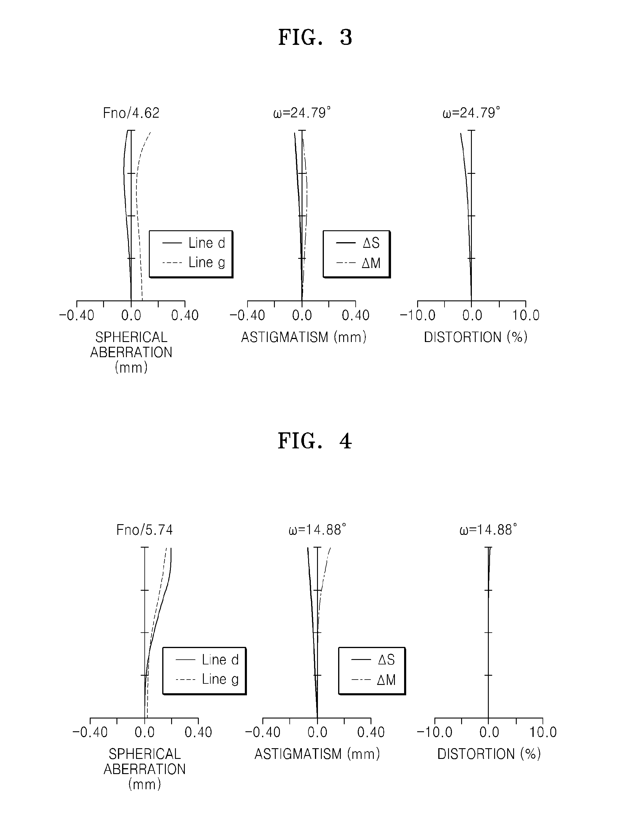
[0076]Table 2 shows the lens data for Embodiment 1. In addition, FIG. 1 is a cross-sectional view of a zoom lens at a wide angle end, according to Embodiment 1. FIG. 2 is an aberration diagram of the zoom lens at the wide angle end, according to Embodiment 1. FIG. 3 is an aberration diagram of the zoom lens at an intermediate zoom position, according to Embodiment 1. FIG. 4 is an aberration diagram of the zoom lens at a telephoto end, according to Embodiment 1.

TABLE 2[Numerical Embodiment 1]Surface DateSurface No.rdndνdObject Surface∞∞ 146.3361.2001.7291654.67 217.3777.021 3*231.6651.2001.5831359.00 4*21.6654.000 526.9953.8111.8061033.27 670.117Variable 7*16.3583.4321.6899753.00 8*−72.6610.872 995.6140.8001.6727032.171018.4182.30011∞Variable 12*43.1171.0001.6847531.221317.9334.2701.4970081.6114−17.933Variable15−147.5181.5411.8466623.7816−23.3821.0001.8061140.731727.038Variable18132.9372.7311.7291654.6719−53.1181.0001.5989530.0520−348.46518.000 21∞2.0001.5168064.2022∞3.200Upper Surfa...

embodiment 2

[0077]Table 3 shows the lens data for Embodiment 2. In addition, FIG. 5 is a cross-sectional view of a zoom lens at a wide angle end, according to Embodiment 2. FIG. 6 is an aberration diagram of the zoom lens at the wide angle end, according to Embodiment 2. FIG. 7 is an aberration diagram of the zoom lens at an intermediate zoom position, according to Embodiment 2. FIG. 8 is an aberration diagram of the zoom lens at a telephoto end, according to Embodiment 2.

TABLE 3[Numerical Embodiment 2]Surface DataSurface No.rdndνdobject Surface∞∞ 145.7211.5321.7200043.69 217.3657.856 3*180.6451.5001.6935053.19 4*28.4149.296 538.8823.7551.8466623.78 681.886Variable 722.8863.4901.7200043.69 8−117.1451.335 9*45.2893.2311.5163364.0710−27.1291.0001.7204734.711127.1294492.00012∞Variable(Aperture)1337.7480.8001.6989530.131414.7584.9481.5163364.07 15*−25.712Variable16−212.4541.9841.8466623.7817−20.2350.7941.8340027.161845.490Variable1946.0844.1051.4874970.2420−46.0841.3001.7204734.71213171.094218.011 ...

embodiment 3

[0078]Table 4 shows the lens data for Embodiment 3. FIG. 9 is a cross-sectional view of a zoom lens at a wide angle end, according to Embodiment 3. FIG. 10 is an aberration diagram of the zoom lens at the wide angle end, according to Embodiment 3. FIG. 11 is an aberration diagram of the zoom lens at an intermediate zoom position, according to Embodiment 3. FIG. 12 is an aberration diagram of the zoom lens at a telephoto end, according to Embodiment 3.

TABLE 4[Numerical Embodiment 3]Surface DataSurface No.rdndνdObject∞∞Surface 131.7481.2001.8042046.50 214.1467.474 3*180.3462.0001.6935053.19 4*24.2054.077 527.3483.1571.8051825.48 663.982Variable 7*19.6694.3951.6935053.19 8*−33.2310.858 9−69.5830.8001.6727022.171036.3582.30011∞Variable(Aperture) 12*59.9131.0461.6889321.081316.2085.0001.4070081.6114−16.208Variable15−103.9772.0051.8466623.7816−18.8331.0001.8061140.731732.211Variable18304.8141.9241.7291654.6719−77.2911.0001.6989530.0320482.81918.050 21∞2.0001.5168064.2022∞3.200Upper∞Surfac...


PUM


Abstract

A zoom lens includes, sequentially from an object side, a first lens group having negative refractive power, a second lens group having positive refractive power, a third lens group having negative refractive power; and a fourth lens group having positive refractive power. When zoom is varied from a wide-angle end to a telephoto end, positions of the first lens group and the fourth lens group are fixed on an optical axis. The second lens group includes, sequentially from the object side, a second A lens group having positive refractive power and a second B lens group having positive refractive power, and the second B lens group is moved in the optical axis direction to perform a focusing function from an object disposed in a close range to an object disposed at infinity. The third lens group is shifted in a direction perpendicular to the optical axis to correct image blur.

Description

CROSS-REFERENCE TO RELATED PATENT APPLICATIONS[0001]This application claims the priority benefit of Japanese Patent Application No. 2012-0265560, filed on Dec. 4, 2012, in the Japanese Patent Office and Korean Patent Application No. 10-2013-0066061, filed on Jun. 10, 2013, in the Korean Intellectual Property Office, the disclosures of which are incorporated herein in their entirety by reference.BACKGROUND[0002]1. Field[0003]One or more embodiments of the invention relate to a zoom lens and an electronic device including the same, and more particularly, to a zoom lens having a function to correct blur in a captured image due to vibration. More particularly, various embodiments of the invention relate to a zoom lens that includes four lens groups (i.e., a first lens group to a fourth lens group), where positions of the first and fourth lens groups are fixed when zoom is varied, and an electronic device including the zoom lens.[0004]2. Description of the Related Art[0005]Japanese Paten...

Claims


Application Information

Patent Timeline
Patent Type & Authority Applications(United States)
IPC IPC(8): G02B15/167G02B27/64
CPCG02B27/646G02B15/167G02B15/177G02B15/144511G02B15/22
Inventor HAGIWARA, HIROYUKI
Owner SAMSUNG ELECTRONICS CO LTD
Why Eureka
Try Eureka