Information processing apparatus and method for correcting vibration
a technology of information processing apparatus and vibration correction, which is applied in the field of image processing apparatus and image processing method, can solve the problems of high calculation cost, continuous shooting speed drop, and inability to accurately correct the
- Summary
- Abstract
- Description
- Claims
- Application Information
AI Technical Summary
Benefits of technology
Problems solved by technology
Method used
Image
Examples
first embodiment
Arrangement of Camera
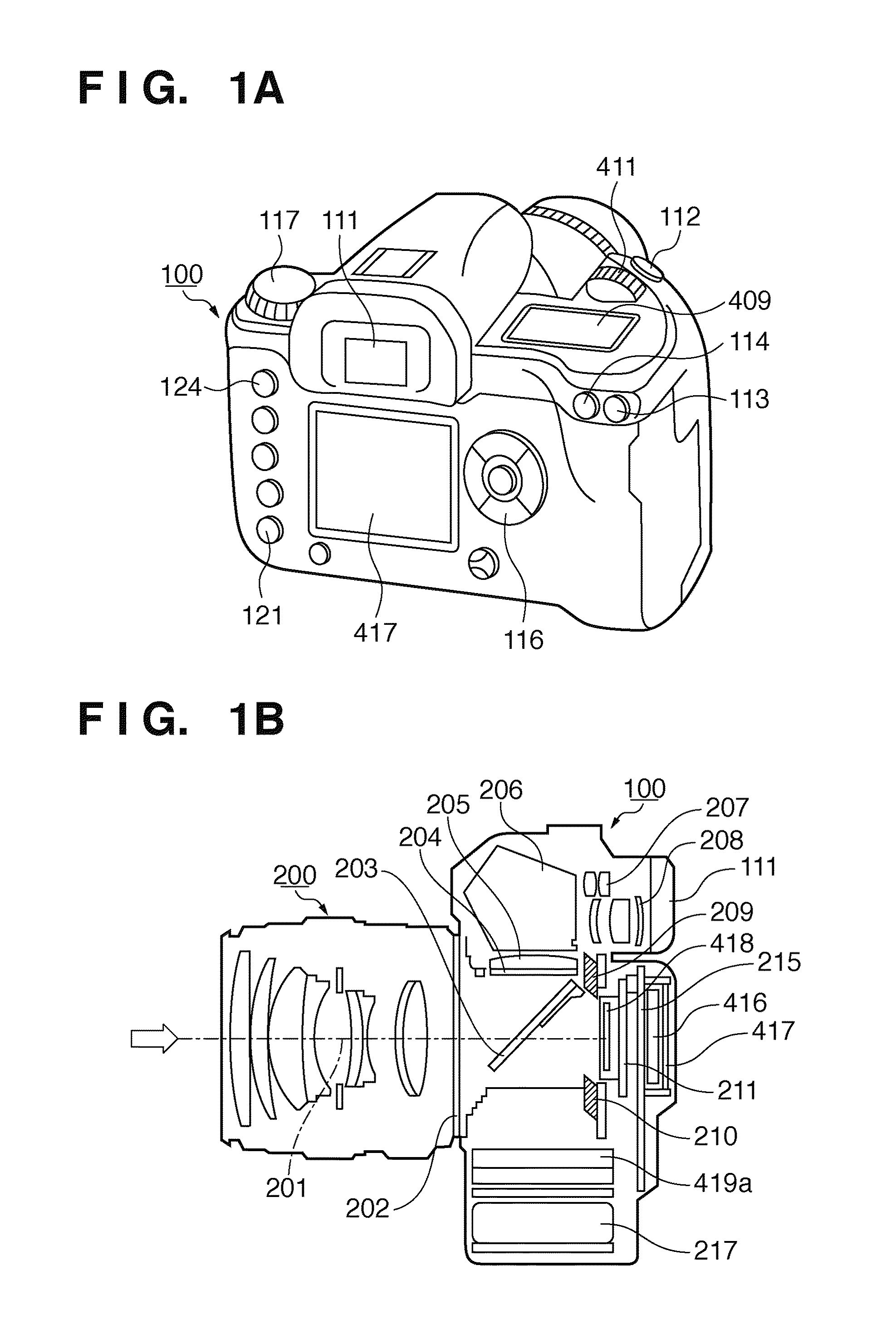
[0033]FIGS. 1A and 1B are respectively an external view and cross-sectional view of a digital camera.
[0034]A viewfinder eyepiece 111, auto-exposure (AE) lock button 114, button 113 used to select auto-focus (AF) points, and release button 112 used to start an imaging operation are arranged on the top portion of a camera body 100. Also, an imaging mode selection dial 117, external display unit 409, digital dial 411, and the like are arranged.
[0035]The digital dial 411 serves as a multi-function signal input unit which is used to input a numerical value to the camera in cooperation with another operation button and to switch an imaging mode. The external display unit 409 as an LCD panel displays imaging conditions including a shutter speed, stop, and imaging mode, and other kinds of information.
[0036]On the back surface of the camera body 100, a liquid crystal display (LCD) monitor 417 which displays an image caught by the camera, that captured by the camera, vari...
second embodiment
[0121]Image processes according to the second embodiment of the present invention will be described below. Note that the same reference numerals in the second embodiment denote the same components as those in the first embodiment, and a detailed description thereof will not be repeated.
[0122]The first embodiment has explained the method of implementing the process equivalent to coded exposure using time-divisionally exposed images and a divide pattern. Also, the first embodiment has explained the example of the divide pattern generation method. The second embodiment will explain another divide pattern generation method.
[0123]FIGS. 14A to 14C are views for explaining images used to generate motion information.
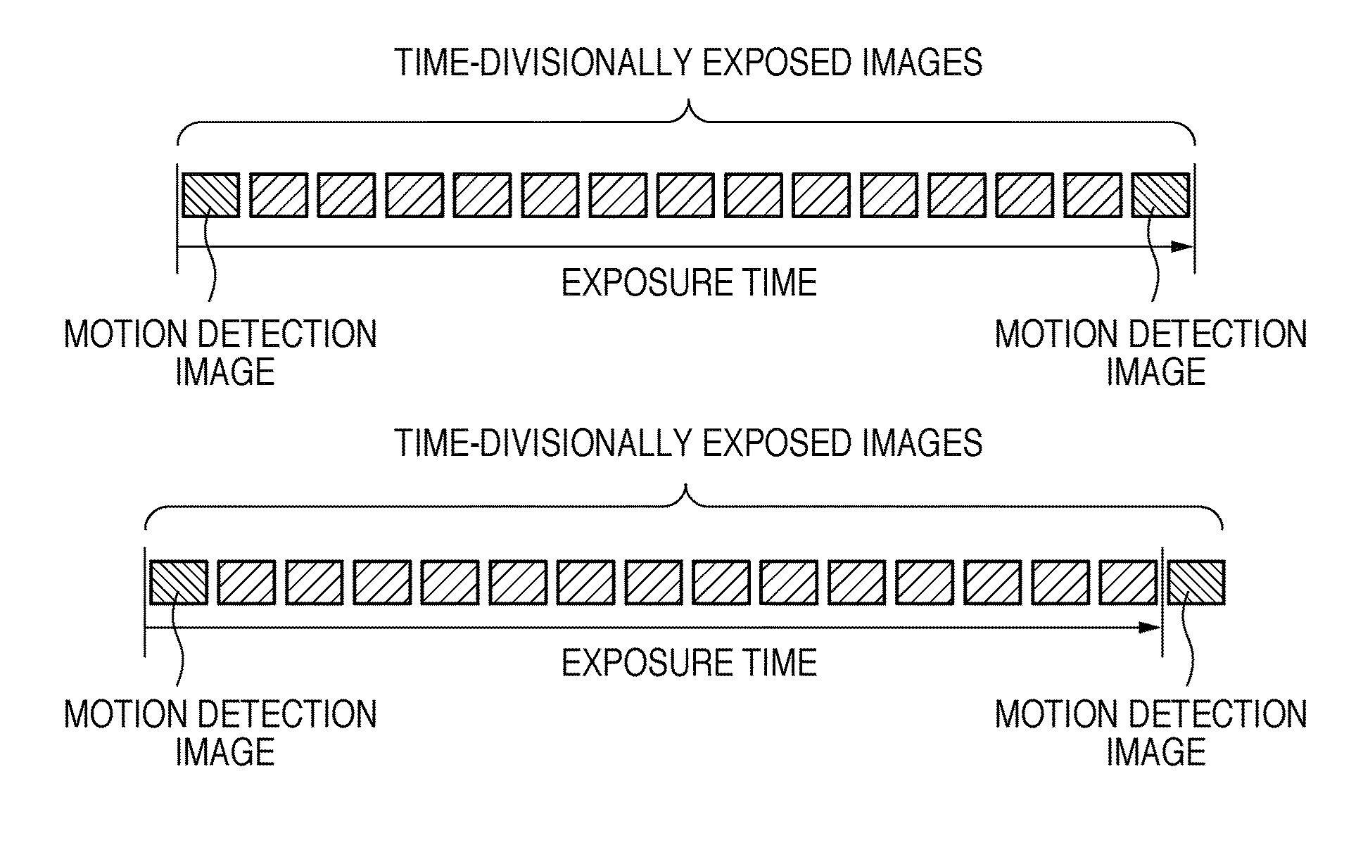
[0124]In order to obtain motion information, at least an image captured when a shutter transits from a close state to an open state and that captured when the shutter transits from the open state to the close state are required. That is, when motion information is generated from...
third embodiment
[0128]Image processes according to the third embodiment of the present invention will be described below. Note that the same reference numerals in the third embodiment denote the same components as those in the first and second embodiments, and a detailed description thereof will not be repeated.
[0129]The above embodiments have explained the method of generating a random pattern as a divide pattern. When synthesis images and motion detection images are randomly divided, the motion detection images are divided irrespective of displacement amounts of images. As a result, an actual exposure amount is reduced, and an adjustment coefficient of a gain adjustment process required to compensate for the reduced exposure amount is increased, thus posing a problem of an increase in noise.
[0130]When a plurality of short exposure images are acquired by time-division exposure, and are divided to implement an image stabilization process, images within a predetermined exposure time can always be ac...
PUM
 Abstract
Description
Claims
Application Information
 - R&D
- Intellectual Property
- Life Sciences
- Materials
- Tech Scout
- Unparalleled Data Quality
- Higher Quality Content
- 60% Fewer Hallucinations
Browse by: Latest US Patents, China's latest patents, Technical Efficacy Thesaurus, Application Domain, Technology Topic, Popular Technical Reports.
© 2025 PatSnap. All rights reserved.Legal|Privacy policy|Modern Slavery Act Transparency Statement|Sitemap|About US| Contact US: help@patsnap.com


