Zoom lens and imaging apparatus

a zoom lens and imaging apparatus technology, applied in the field of zoom lenses and imaging apparatuses, can solve the problems of large aberration deterioration caused by the decentrating of each composed lens group, and it is difficult to acquire a zoom lens having a sufficient optical performance, so as to achieve well balanced image forming performance, prevent the effect of growing in the diameter of the front lens and suppressing the quantity of aberration at the time of camera shake correction

Inactive Publication Date: 2007-01-04
SONY CORP
View PDF2 Cites 5 Cited by
  • Summary
  • Abstract
  • Description
  • Claims
  • Application Information

AI Technical Summary

Benefits of technology

[0014] Consequently, the zoom lens of the embodiment of the present invention can perform camera shake correction, and can be shaped to be thin. Moreover, the zoom lens can prevent the growing in size of the drive mechanism of the shift lens group, and can easily control a shift quantity of the shift lens group for the camera shake correction.
[0016] Thereby, the imaging apparatus can perform camera shake correction, and the imaging apparatus can be shaped to be small by preventing the growing of the size of the mechanism of driving the shift lens group. Moreover, the imaging apparatus can be formed to be thin. Furthermore, it is easy to control the shift quantity of the shift lens group for the camera shake correction.
[0017] According to still another embodiment of the present invention, the first lens group having the negative refractive power, the second lens group having the negative refractive power, the third lens group having a positive refractive power, and a fourth lens group having a positive refractive power are arranged in the order from the object side, and consequently the zoom lens has a well balanced image forming performance.
[0018] According to further another embodiment of the present invention, if it is supposed that f1 denotes a focus distance of the first lens group and f2 denotes a focus distance of the second lens group, the focus distances f1 and f2 satisfy a conditional expression (2): 0.1<|f1 / f2|<1.2. Consequently, the growing in a front lens diameter can be prevented, and the correction of distortion can be performed in a good state. Furthermore, the occurrence quantity of aberration at the time of camera shake correction can be suppressed.
[0019] According to another embodiment of the present invention, if it is supposed that f1 denotes a focus distance of the first lens group and fw denotes a focus distance of the whole lens system in a maximum wide angle state, the focus distances f1 and fw satisfy a conditional expression (3): 3.8<|f1 / fw|<5.0. Consequently, the growing in the sizes of a front lens diameter and the reflection member can be prevented, and the correction of distortion can be performed in a good state.
[0020] The imaging apparatus according to the above embodiment may further have camera shake detection means, camera shake correction control means and a camera shake correction drive unit. The camera shake detection means detects a shake of the imaging device. The camera shake control means calculates a shake correction angle for correcting image blurring caused by the shake of the imaging device detected by the camera shake detection means to transmit a drive signal to a drive unit so as to situate the shift lens group at a position based on the shake correction angle. The camera shake drive unit shifts the shift lens group in a direction perpendicular to the optical axis based on the drive signal. Consequently, the imaging apparatus can correct the blurring of an image caused by a shake of the imaging device caused by a camera shake, and the imaging apparatus can acquire a high quality image, which is in a good in-focus state and has corrected various aberrations in a good state.

Problems solved by technology

However, as described above, it is difficult to acquire a zoom lens having a sufficient optical performance only by simply combining the thin-shaped formation by the bending of the optical path in the reflection member and the image shifting method by lens shifting.
In particular, aberration deterioration caused by decentrating of each composed lens group becomes large.

Method used


Image

  • Zoom lens and imaging apparatus
  • Zoom lens and imaging apparatus
  • Zoom lens and imaging apparatus

Examples


first embodiment

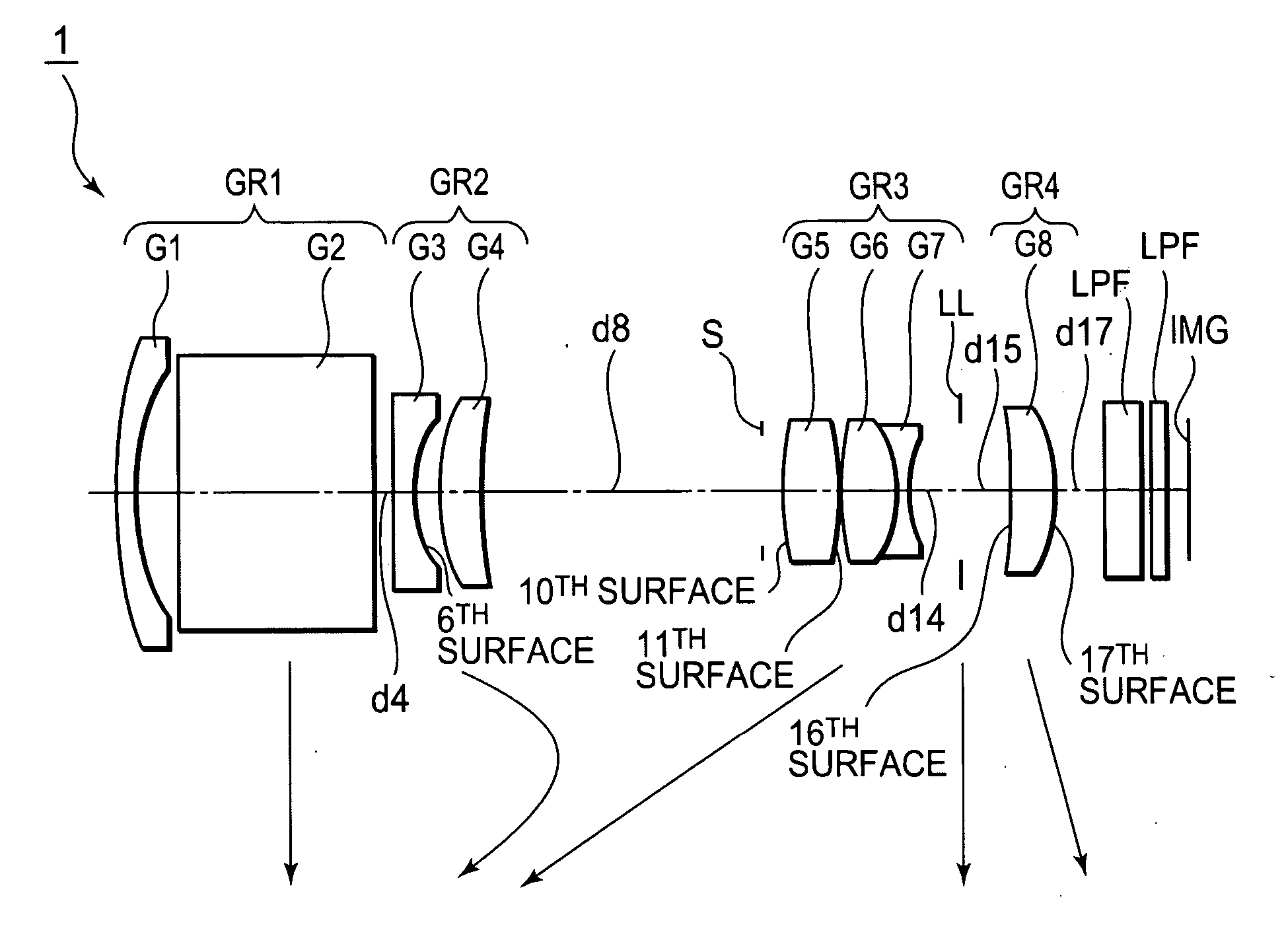
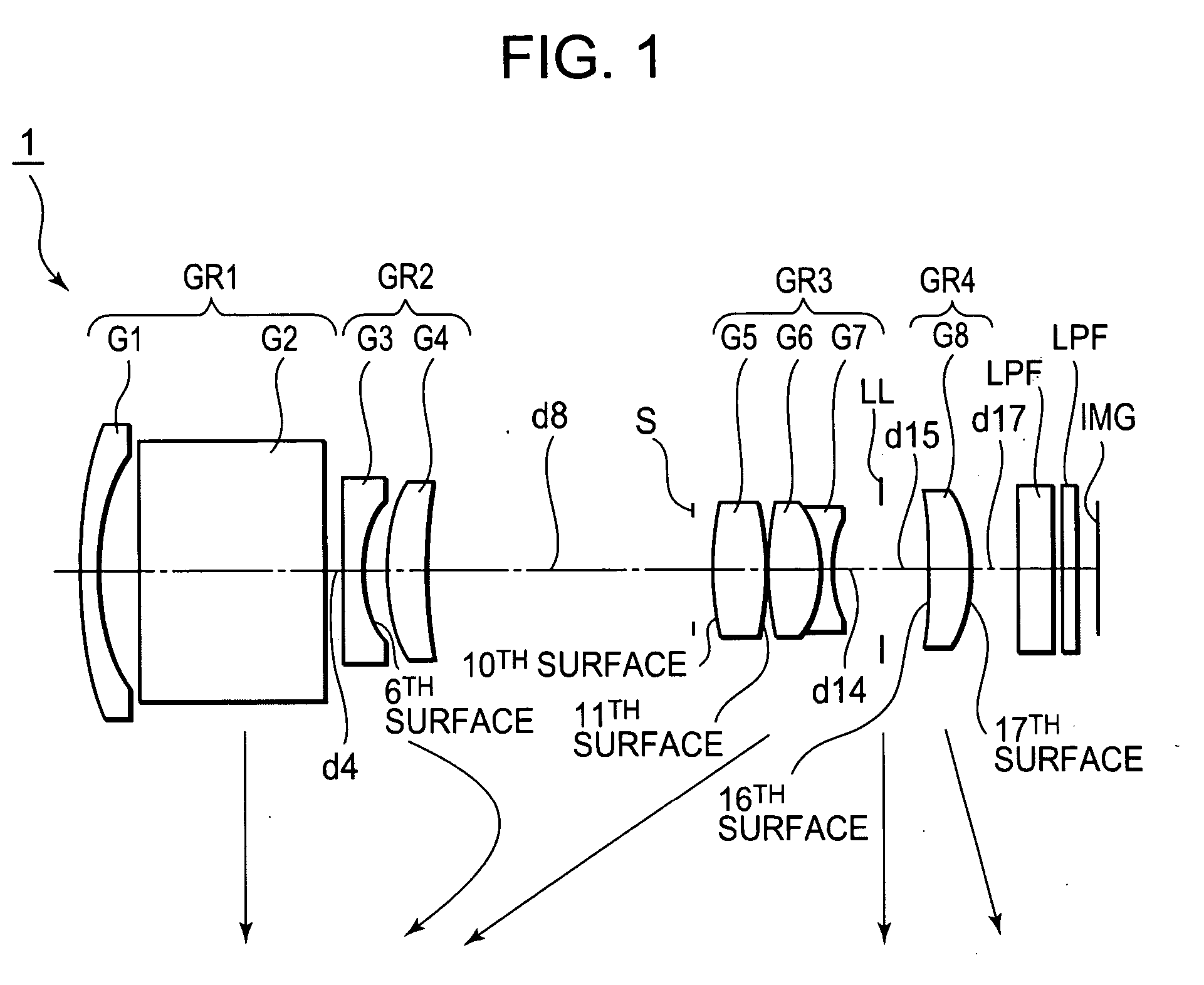
[0059]FIG. 1 shows a zoom lens 1 of the present invention.

[0060] The zoom lens 1 is composed of a first lens group GR1 having a negative refractive power, a second lens group GR2 having a negative refractive power, a third lens group GR3 having a positive refractive power, and a fourth lens group GR4 having a light amount adjustment member LL and a positive refractive power, each arranged in the order from the object side. The first lens group GR1 is composed of a negative lens G1 and a rectangular prism G2 for bending an optical axis by 90°. The second lens group GR2 is composed of a negative lens G3 having an aspherical surface on the image side, and a positive lens G4. The third lens group GR3 is composed of a positive lens G5 having aspherical surfaces on both the surfaces thereof, and a cemented lens of a positive lens G6 and a negative lens G7. The fourth lens group GR4 is composed of a plastic positive lens G8 having aspherical surfaces on both the surfaces thereof. When a le...


PUM


Abstract

A zoom lens having at least a first lens group including a reflection member for bending an optical axis fixedly during zooming and having a negative refractive power, a second lens group having a negative refractive power, and a third lens group arranged in the order from an object side is provided. In the zoom lens, an image can be shifted into a direction perpendicular to the optical axis by moving either of the second and the third lens groups (“shift lens group”) in a direction perpendicular to the optical axis, and a following conditional expression (1) is satisfied, 0.5<(1−βα)×βb<3.0,  (1) where: βα: a magnification of the shift lens group in a maximum telephoto state, and βb: a magnification of a lens group arranged on an image surface side of the shift lens group in the maximum telephoto state.

Description

CROSS REFERENCES TO RELATED APPLICATIONS [0001] The present document contains subject matter related to Japanese Patent Application JP 2005-186572 filed in the Japanese Patent Office on Jun. 27, 2005, the entire contents of which being incorporated herein by reference. BACKGROUND OF THE INVENTION [0002] 1. Field of the Invention [0003] The present invention relates to a novel zoom lens and a novel imaging apparatus. In particular, the present invention relates to a zoom lens and an imaging apparatus equipped with the zoom lens. The zoom lens includes the function of correcting or reducing the blurring of a photographed image owing to camera shaking, or a camera shake correction / reduction function. The zoom lens is suitable for a photographing optical system of digital input-output equipment such as a digital still camera, a digital video camera and the like, and is compact, which achieves dimensions being thin in the depth direction of a camera. [0004] 2. Description of Related Art ...

Claims


Application Information

Patent Timeline
Patent Type & Authority Applications(United States)
IPC IPC(8): G02B15/14
CPCG02B15/177G02B13/22G02B15/144513
Inventor IWASAWA, YOSHITO
Owner SONY CORP
Why Eureka
Try Eureka