Blur correcting device, blur correcting method, and image pickup apparatus

a pickup apparatus and blur correction technology, applied in the field of blur correction devices, blur correction methods, image pickup apparatuses, can solve the problems of difficult to obtain excellent blur-free picked-up images, difficult to properly perform blur correction, and inability to properly correct blur, etc., to achieve correct optical image blur, increase displacement range, and increase displacement range

Inactive Publication Date: 2011-06-14
SONY CORP
View PDF18 Cites 6 Cited by
  • Summary
  • Abstract
  • Description
  • Claims
  • Application Information

AI Technical Summary

Benefits of technology

[0008]Accordingly, it is desirable to provide a blur correcting device, a blur correcting method, and an image pickup apparatus that make it possible to perform blur correction in which both reduction in degradation of a picked-up image and improvement in blur correction performance can be achieved.
[0009]A blur correcting device according to an embodiment of the present invention includes a shake detecting unit configured to detect a shake and output a detection signal indicating a result of the detection; a drive unit configured to displace a relative positional relationship between a lens unit and an image pickup element relative to an optical axis such that a position of an optical image formed on an image pickup surface of the image pickup element is displaced on the image pickup surface; and a control unit configured to increase a displacement range when the amount of shake indicated by the detection signal is larger than a predetermined level, displace the relative positional relationship between the lens unit and the image pickup element within the increased displacement range in accordance with the detection signal, and thereby correct a blur of the optical image on the image pickup surface caused by the shake detected by the shake detecting unit.
[0011]A blur correcting method according to another embodiment of the present invention includes the steps of detecting a shake and outputting a detection signal indicating a result of the detection; displacing a relative positional relationship between a lens unit and an image pickup element relative to an optical axis such that a position of an optical image formed on an image pickup surface of the image pickup element is displaced on the image pickup surface; and increasing a displacement range when the amount of shake indicated by the detection signal is larger than a predetermined level, displacing the relative positional relationship between the lens unit and the image pickup element within the increased displacement range in accordance with the detection signal, and thereby correcting a blur of the optical image on the image pickup surface caused by the detected shake.
[0012]An image pickup apparatus according to another embodiment of the present invention includes a shake detecting unit configured to detect a shake and output a detection signal indicating a result of the detection; a drive unit configured to displace a relative positional relationship between a lens unit and an image pickup element relative to an optical axis such that a position of an optical image formed on an image pickup surface of the image pickup element is displaced on the image pickup surface; a signal processing unit configured to perform camera signal processing using an image signal generated by the image pickup element; and a control unit configured to increase a displacement range when the amount of shake indicated by the detection signal is larger than a predetermined level, displace the relative positional relationship between the lens unit and the image pickup element within the increased displacement range in accordance with the detection signal, and thereby correct a blur of the optical image on the image pickup surface caused by the shake detected by the shake detecting unit.
[0013]According to the embodiments of the present invention, the displacement range of the lens unit or the image pickup element is changed in accordance with a shake detected by the shake detecting unit, so that the displacement range is widened when the amount of the detected shake is large. When the amount of the detected shake is small, the displacement range is narrowed, so that blur correction which does not significantly degrade an image is performed. On the other hand, when the amount of the detected shake is large, the displacement range is widened, so that high-performance blur correction is performed. Thus, it is possible to perform blur correction in which both reduction in image degradation and improvement in blur correction performance can be achieved.

Problems solved by technology

When a displacement range of a correction lens is limited in accordance with a focal length so as to prevent blur correction from being performed under the condition of large optical aberration, if, for example, an image pickup apparatus considerably shakes while an image pickup operation is being performed at the wide end where a large optical aberration occurs, since the displacement of the correction lens is limited, it is difficult to properly perform blur correction.
This means that when the zoom position is at the wide end, if, for example, the user performs an image pickup operation while walking, blur correction is not performed when the image pickup apparatus shakes considerably.
As a result, it is difficult to obtain an excellent blur-free picked-up image.

Method used


Image

  • Blur correcting device, blur correcting method, and image pickup apparatus
  • Blur correcting device, blur correcting method, and image pickup apparatus
  • Blur correcting device, blur correcting method, and image pickup apparatus

Examples


Embodiment Construction

[0024]Hereinafter, embodiments for carrying out the present invention will be described in the following order:

[0025]1. Configuration of image pickup apparatus

[0026]2. Operation of blur correcting device

[0027]3. First operation of blur correcting device

[0028]4. Second operation of blur correcting device

[0029]5. Another operation for determining limiting condition

(1. Configuration of Image Pickup Apparatus)

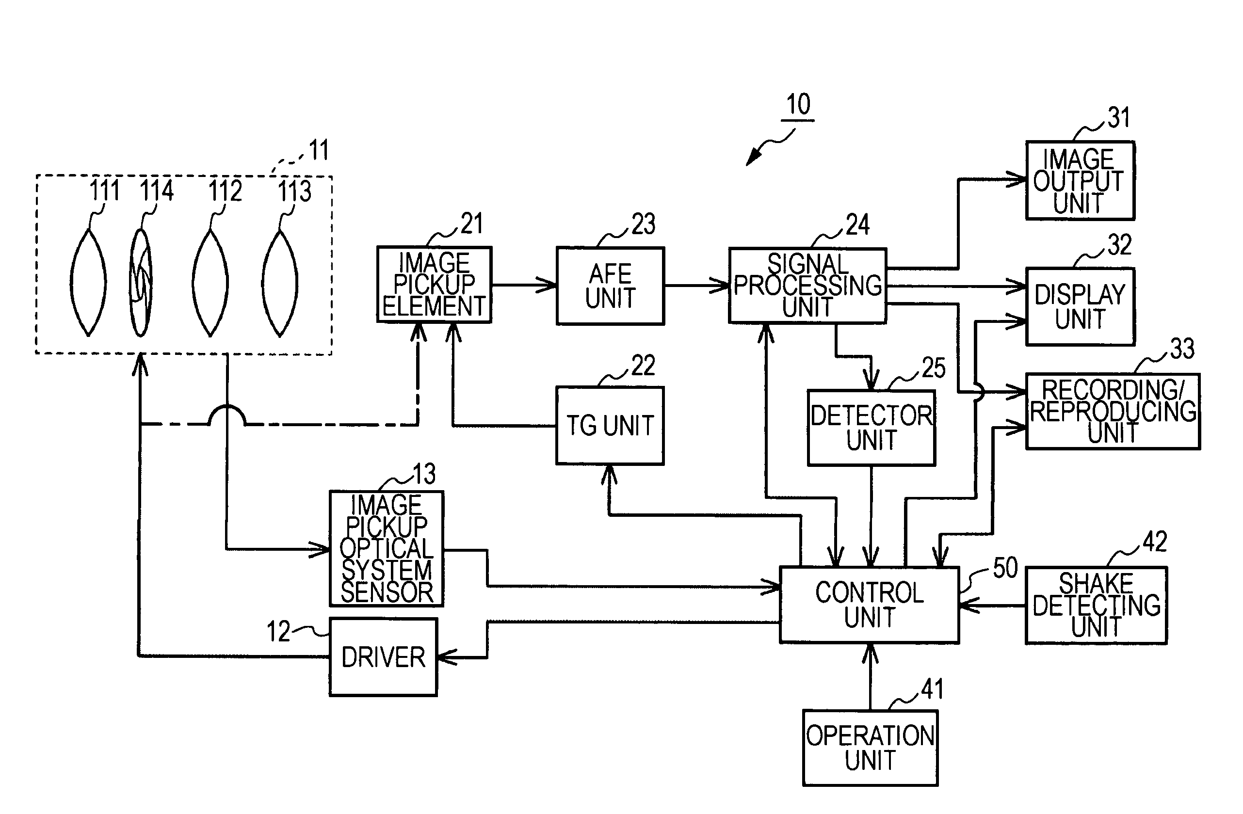
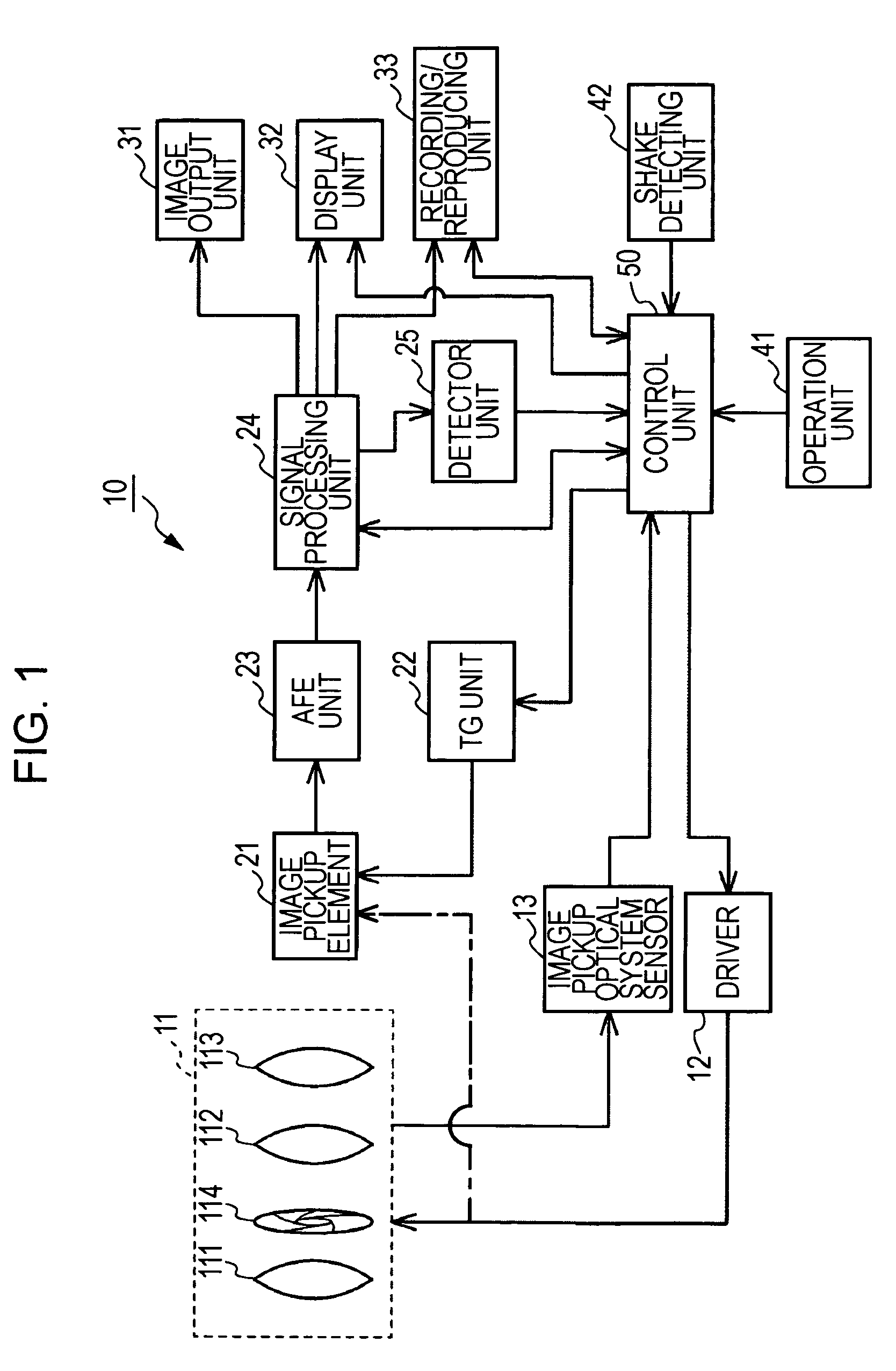
[0030]FIG. 1 is a block diagram illustrating a configuration of an image pickup apparatus including a blur correcting device according to an embodiment of the present invention. An image pickup apparatus 10 includes an image pickup optical system block 11, a driver 12, an image pickup optical system sensor 13, an image pickup element 21, a timing signal generating (TG) unit 22, an analog front-end (AFE) unit 23, a signal processing unit 24, and a detector unit 25. The image pickup apparatus 10 further includes an image output unit 31, a display unit 32, a recording / reproducing unit...


PUM


Abstract

A blur correcting device includes a shake detecting unit configured to detect a shake and output a detection signal indicating a result of the detection; a drive unit configured to displace a relative positional relationship between a lens unit and an image pickup element relative to an optical axis such that a position of an optical image formed on an image pickup surface of the image pickup element is displaced on the image pickup surface; and a control unit configured to increase a displacement range when the amount of shake indicated by the detection signal is larger than a predetermined level, displace the relative positional relationship between the lens unit and the image pickup element within the increased displacement range in accordance with the detection signal, and thereby correct a blur of the optical image on the image pickup surface caused by the shake detected by the shake detecting unit.

Description

CROSS-REFERENCE TO RELATED APPLICATION[0001]The present application claims priority from Japanese Patent Application No. JP 2008-315428 filed in the Japanese Patent Office on Dec. 11, 2008, the entire content of which is incorporated herein by reference.BACKGROUND OF THE INVENTION[0002]1. Field of the Invention[0003]The present invention relates to blur correcting devices, blur correcting methods, and image pickup apparatuses. In particular, the present invention relates to techniques which make it possible to obtain a blur-corrected image even when an image pickup apparatus shakes considerably.[0004]2. Description of the Related Art[0005]In the related art, to prevent the position of an optical image on an image pickup surface from being moved by a shake, a blur correcting mechanism of an image pickup apparatus has, for example, a correction lens for correcting an optical axis.[0006]In this blur correcting mechanism, an angle by which the optical axis can be corrected by the correc...

Claims


Application Information

Patent Timeline
Patent Type & Authority Patents(United States)
IPC IPC(8): G03B17/00
CPCG02B27/646H04N5/23248H04N5/23287H04N5/23261H04N5/23283H04N5/23258H04N23/68H04N23/6812H04N23/6815H04N23/686H04N23/687
Inventor TSUCHIHASHI, KOUSUKE
Owner SONY CORP
Why Eureka
Try Eureka