Image-taking apparatus

a technology of image data and imaging device, which is applied in the field of image-taking apparatus, can solve the problems of difficult to thin the camera body, difficult for users to hold still such a slim type of digital camera provided with a refractive optical system, and the possibility of camera shake, so as to achieve the effect of reducing the thickness and further suppressing the noise in the image data generated by the imaging devi

Active Publication Date: 2010-07-27
FUJIFILM HLDG CORP +1
View PDF5 Cites 5 Cited by
  • Summary
  • Abstract
  • Description
  • Claims
  • Application Information

AI Technical Summary

Benefits of technology

[0014]a correction lens that is disposed between the objective lens and the imaging device and capable of moving in parallel with the imaging surface thereby correcting a blur in a subject image formed on the imaging surface caused by the shake of the image-taking apparatus;
[0030]As described above, it is possible to provide an image-taking apparatus having a refractive optical system, which is reduced in thickness while having a shake correction function.

Problems solved by technology

However, when it comes to a conventional digital camera having: a charge-coupled device (CCD) that is one type of the imaging device; and linearly arranged lenses that form an image of subject light coming through an objective lens on an imaging surface of the CCD, there is a problem that it is difficult to thin the camera body even if it can be made smaller.
However, it is more difficult for a user to hold still such a slim type of digital camera provided with a refractive optical system (refractive type of digital camera), as compared to the digital camera provided with a shooting optical system having linearly arranged lenses (linear type of digital camera).
Therefore, when the refractive type of digital camera is in use, camera shake is very likely to occur when a release button is pressed.
Additionally, the linear type of digital camera is not free from camera shake either and therefore, it has been desired to provide a shake correction function in the camera body.
In contrast, even though the refractive type of digital camera is more susceptible to camera shake, a shake correction function for curing such susceptibility is not yet devised and thus desired.
However, the digital camera employing a refractive optical system needs space in the thickness direction of the camera body to accommodate drivers for driving a zoom lens, a focus lens, a diaphragm, a shutter etc., in which the drivers are disposed around the lenses of the refractive optical system.
Therefore, it is difficult to add a driver for shake correction without further increasing the thickness of the camera body.

Method used


Image

  • Image-taking apparatus
  • Image-taking apparatus
  • Image-taking apparatus

Examples


first embodiment

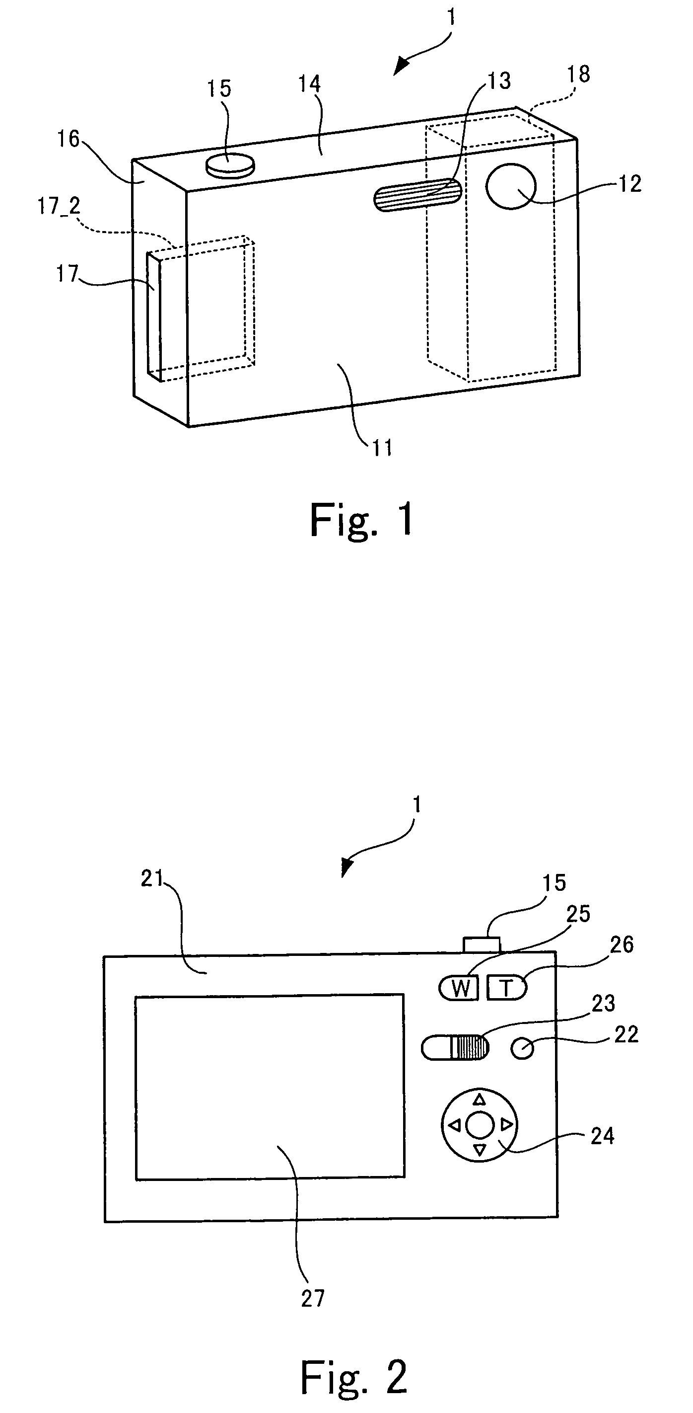
[0042]FIG. 1 is an external perspective view of a digital camera 1 according to the invention.

[0043]FIG. 2 is a diagram showing the back of the digital camera 1 shown in FIG. 1.

[0044]As shown in FIG. 1, a front surface 11 of the digital camera 1 is provided with an objective lens 12 for guiding subject light to a lens group disposed inside the digital camera 1, a flash window 13 through which a flash is emitted to a subject. A top surface 14 of the digital camera 1 is provided with a release button 15. A still image is taken at the press of the release button 15.

[0045]Formed on a side surface 16 of the digital camera 1 is a recording-media slot 17 into which a recording medium 17_2 for recording image data is removably inserted.

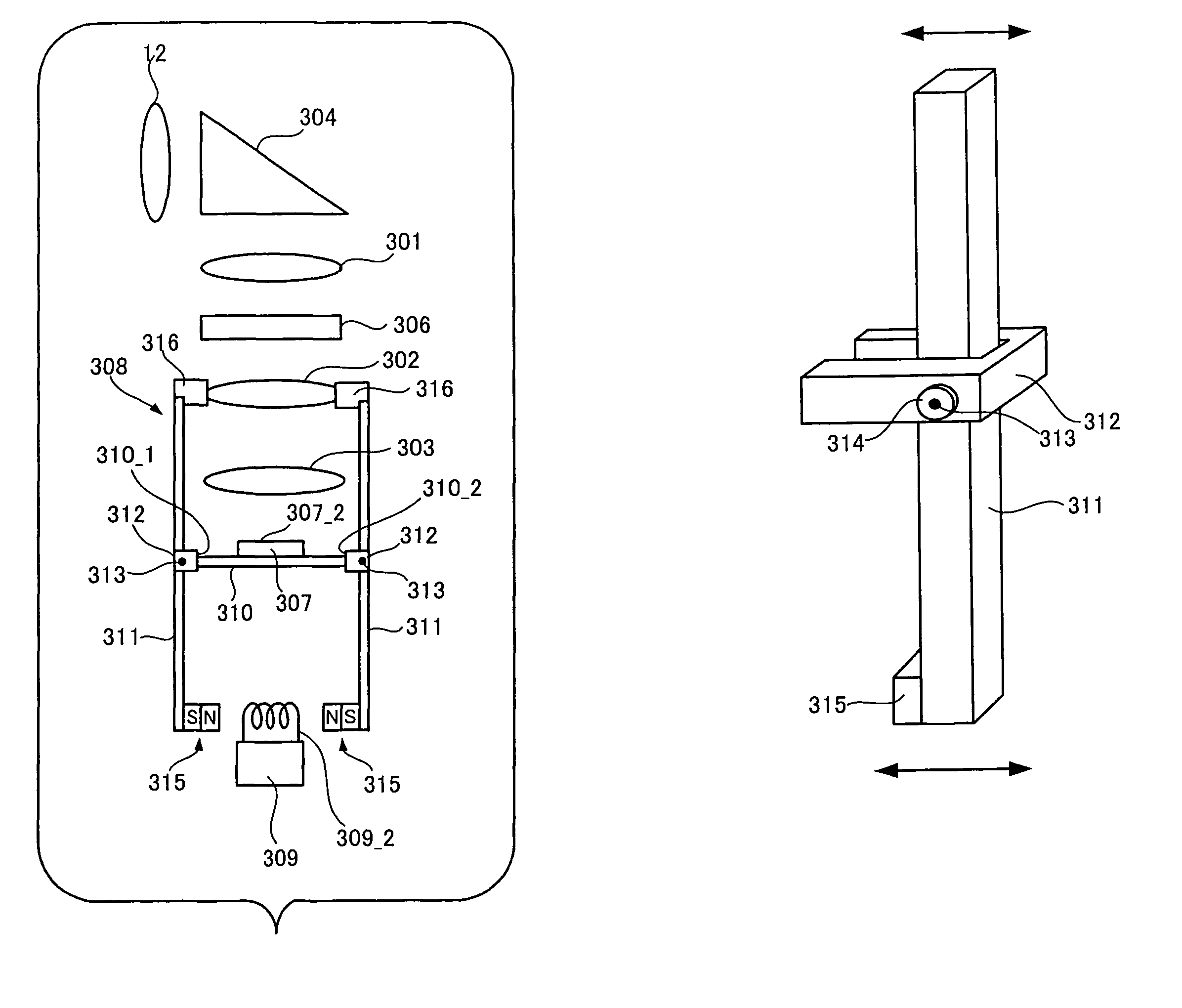
[0046]Disposed inside the digital camera 1 is a refractive optical system 18, which will be described later in detail.

[0047]As shown in FIG. 2, aback surface 21 of the digital camera 1 is provided with a power button 22 and a mode switch 23. The power button ...

second embodiment

[0095]Next, the invention will be described.

[0096]The description of a digital camera according to the second embodiment of the invention will focus on a feature different from the digital camera 1 of the first embodiment. The same elements of the second embodiment as those of the first embodiment are denoted by the same reference characters as those of the first embodiment.

[0097]FIGS. 9(a) and 9(b) are conceptual diagrams showing the operation of a power transmission system 308_2 of the digital camera according to the second embodiment of the invention.

[0098]The digital camera according to the second embodiment of the invention is provided with the power transmission system 308_2 having an oval cam 317.

[0099]In the power transmission system 308_2, the oval cam 317 is disposed between lens-supporting arms 311 while being supported by a rotation shaft 318. Part of the cam 317 is in contact with the two lens-supporting arms 311. A rotation belt 319 for rotating the cam 317 is attached...

third embodiment

[0110]Next, the invention will be described.

[0111]The description of a digital camera according to the third embodiment will also focus on a feature different from the digital camera 1 of the first embodiment. The same elements of the third embodiment as those of the first embodiment are denoted by the same reference characters as those of the first embodiment.

[0112]FIG. 10 is a conceptual diagram showing the operation of a power transmission system 308_3 of the digital camera according to the third embodiment of the invention.

[0113]The digital camera according to the third embodiment of the invention employs the power transmission system 308_3 having a lens-supporting arm 311 and a spring 323.

[0114]The power transmission system 308_3 has only one lens-supporting arm 311 similar to those described above. This lens-supporting arm 311 extends in parallel with an optical axis of subject light while passing close by a side of a CCD 307, and supports a correction lens 302 via one end 316...


PUM


Abstract

An image-taking apparatus includes: a CCD having an imaging surface; and an image-taking optical system having an objective lens. The apparatus further includes: a shake detector that detects a shake of the image-taking apparatus; and a correction lens disposed between the objective lens and the CCD and moving in parallel with the imaging surface to correct a blur in an image formed on the imaging surface caused by the shake of the image-taking apparatus. The apparatus further includes: an electromagnet disposed behind the CCD and driving the correction lens; a power transmission system that moves the correction lens by transmitting power from the electromagnet to the correction lens; and a correction-lens controller that causes, based on a detection result from the shake detector, the electromagnet to drive the correction lens such that an image whose blur due to the shake is corrected is formed on the imaging surface.

Description

BACKGROUND OF THE INVENTION[0001]1. Field of the Invention[0002]The present invention relates to an image-taking apparatus that generates shooting data in response to shooting operation and includes: an imaging device that has an imaging surface and generates image data by reading a subject image formed on the imaging surface; and an image-taking optical system that has an objective lens and a reflection member and forms an image on the imaging surface by reflecting subject light coming through the objective lens with the reflection member.[0003]2. Description of the Related Art[0004]Digital camera is known as one of the image-taking apparatus. In recent years, attention has been focused on digital cameras that are small as well as slim and thus convenient to carry.[0005]Generally, a digital camera is made smaller by reducing the sizes of components such as lenses in a shooting optical system, members for supporting such components and drivers used in the image-taking optical system...

Claims


Application Information

Patent Timeline
Patent Type & Authority Patents(United States)
IPC IPC(8): G03B17/00H04N5/228
CPCG03B17/17H04N5/23248H04N5/23258H04N5/23287G03B2205/0015G03B2217/005H04N23/68H04N23/6812H04N23/687
Inventor AWAZU, KOUHEIMISAWA, ATSUSHI
Owner FUJIFILM HLDG CORP
Why Eureka
Try Eureka