Twist-grip anchors and methods of use

a technology of twist-grip anchors and anchors, which is applied in the field of twist-grip anchors and methods of use, can solve the problems of difficult to achieve the effect of facilitating movement resistance, reducing the level of engagement, and reducing the risk of fractur

Active Publication Date: 2014-06-05
TC1 LLC
View PDF4 Cites 2 Cited by
  • Summary
  • Abstract
  • Description
  • Claims
  • Application Information

AI Technical Summary

Benefits of technology

[0010]In some embodiments, level of engagement is adjustable by increasing or decreasing the amount of twist. In some embodiments, engagement atraumatically deforms the elongate device in a manner that assists in resistance of movement of the elongate device in relation to the sleeve.

Problems solved by technology

However, such anchors often do not sufficiently grip the lead and the lead grip force is highly dependent on the suturing technique of the physician.
Such suturing is time consuming, tedious and subject to error or variability.
Although such anchors are sometimes more effective in gripping the lead, the anchors can potentially damage the lead or cause severe deformation of the lead body.
In addition, the mechanically actuated anchors are most suited for leads with relatively rigid bodies and are not suitable for leads having more flexible bodies.

Method used


Image

  • Twist-grip anchors and methods of use
  • Twist-grip anchors and methods of use
  • Twist-grip anchors and methods of use

Examples


Embodiment Construction

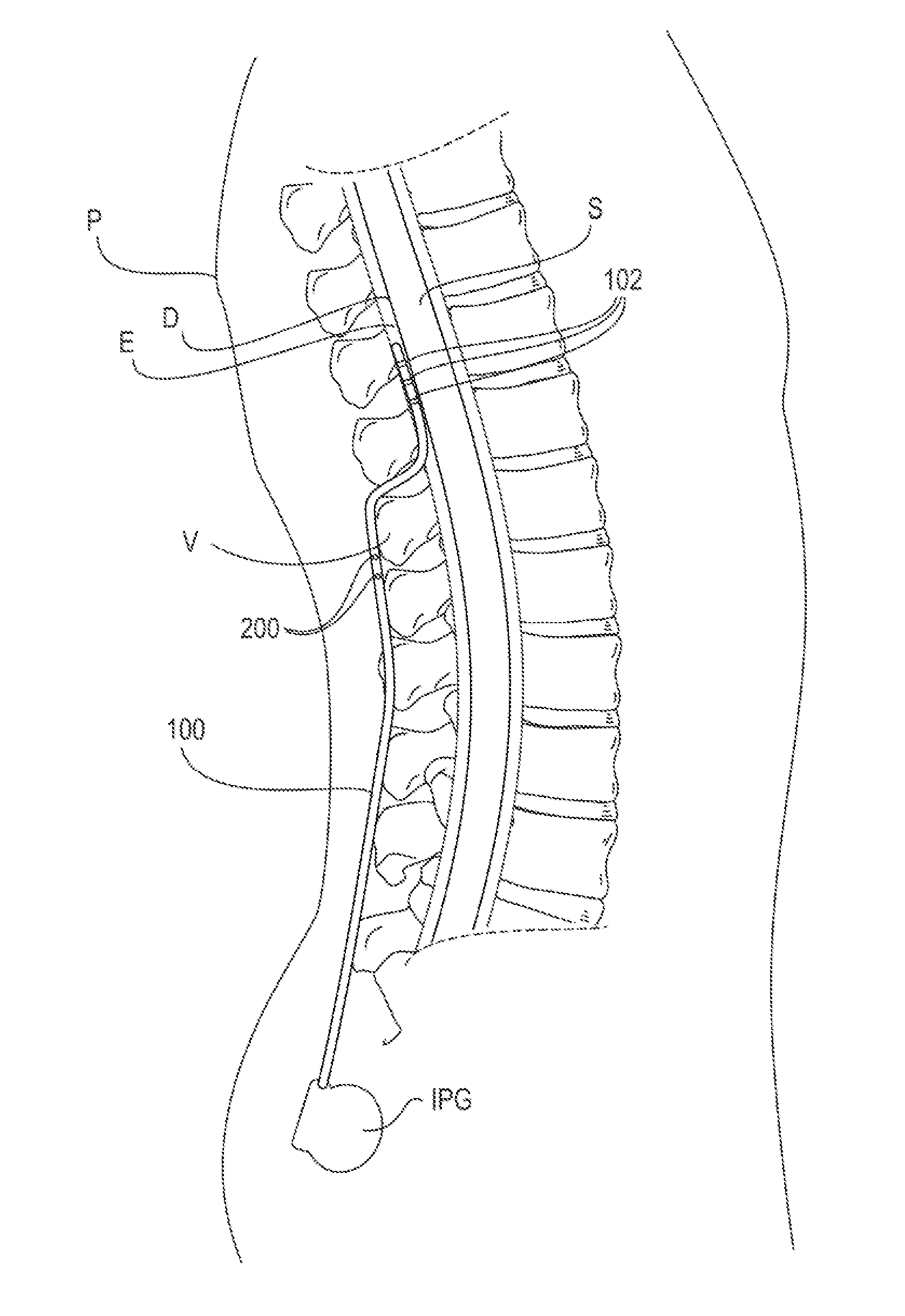
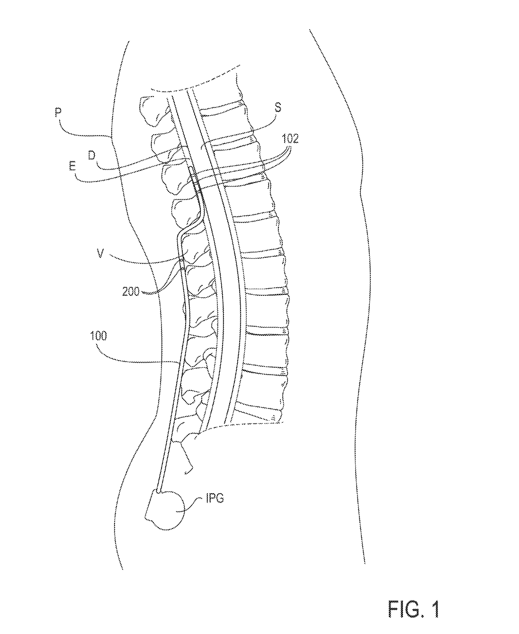
[0027]The present invention provides devices, systems and methods for anchoring implantable medical devices to maintain an implanted position. In some embodiments, the medical devices are stimulation leads which are implanted near a portion of the neural anatomy for providing stimulation thereto. In some embodiments, at least one lead is advanced into the epidural space to apply stimulation energy to the spinal cord itself or to anatomies accessible via the epidural space, such as the dorsal root, dorsal root ganglion or peripheral nerves. FIG. 1 illustrates an example of such an implantable lead 100 advanced into the epidural space E. Here, the lead 100 is shown inserted between the vertebrae V, advanced within the epidural space E and positioned so that electrodes 102 disposed along its distal end are positioned against the dura layer of the spinal cord S. It may be appreciated that the lead 100 may be advanced further, such as to position the electrodes 102 near other spinal anat...


PUM


Abstract

Devices, systems and methods are provided for anchoring implantable medical devices to maintain an implanted position. In particular, twist-grip anchors are provided. In some embodiments, the twist-grip anchor comprises a first support having a first lumen, a second support having a second lumen, and a sleeve having a first end fixedly attached to the first support and a second end fixedly attached to the second support, wherein the first and second supports and the sleeve are aligned to allow the passage of the elongate device through the first lumen, second lumen and sleeve, and wherein rotation of at least the first support twists the sleeve so that the sleeve engages the elongate device in a manner that resists movement of the elongate device in relation to the sleeve. The anchor is then attached to the tissue, such as by suturing.

Description

CROSS-REFERENCES TO RELATED APPLICATIONS[0001]This application claims priority under 35 U.S.C. 119(e) to U.S. Provisional Patent Application No. 61 / 733,813, entitled “Twist-Grip Anchors and Methods of Use”, filed on Dec. 5, 2012, which is incorporated herein by reference.STATEMENT AS TO RIGHTS TO INVENTIONS MADE UNDER FEDERALLY SPONSORED RESEARCH AND DEVELOPMENT[0002]NOT APPLICABLEREFERENCE TO A “SEQUENCE LISTING,” A TABLE, OR A COMPUTER PROGRAM LISTING APPENDIX SUBMITTED ON A COMPACT DISK[0003]NOT APPLICABLEBACKGROUND OF THE INVENTION[0004]Electrical stimulation and drug delivery to portions of the anatomy, particularly the spinal anatomy and peripheral nervous system, often involve the implantation of one or more leads or delivery devices within the patient's body. The leads or delivery devices extend between the target anatomy and an implantable pulse generator (IPG) or drug reservoir which is typically implanted at a remote location. Precise positioning of the leads or delivery ...

Claims


Application Information

Patent Timeline
Patent Type & Authority Applications(United States)
IPC IPC(8): A61B17/04
CPCA61B17/0401A61N1/0558A61N2001/0582
Inventor LEE, JEFFREY J.
Owner TC1 LLC
Why Eureka
Try Eureka