Electric hand with a force sensor

Inactive Publication Date: 2014-06-05
FANUC LTD
View PDF13 Cites 48 Cited by
  • Summary
  • Abstract
  • Description
  • Claims
  • Application Information

AI Technical Summary

Benefits of technology

[0021]Since the electric hand detects a state where the target comes into contact with the finger portion by the force detection value of the force sensor provided in the finger portion, moves the finger portion un

Problems solved by technology

Thus, the contact determination is not easily made, and hence an erroneous operation easily occurs.
Further, in the

Method used


Image

  • Electric hand with a force sensor
  • Electric hand with a force sensor
  • Electric hand with a force sensor

Examples


first embodiment

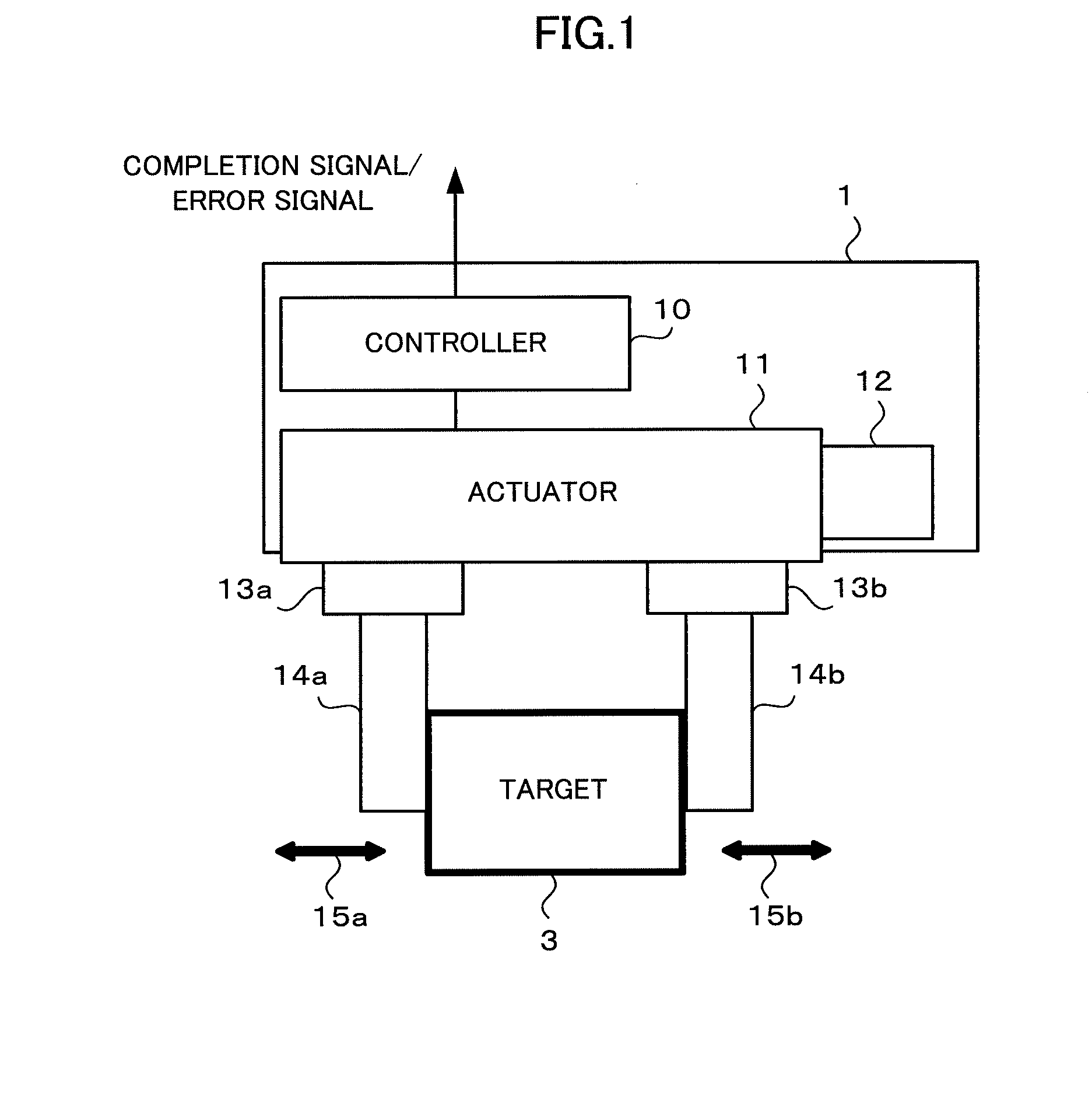
[0030]First, an electric hand with a force sensor according to the present invention will be described with reference to FIG. 1.

[0031]An electric hand 1 includes two opening and closing fingers (a finger 14a and a finger 14b). An actuator 11 includes a motor, a decelerator, and a linear driving mechanism, which are not illustrated in the drawings. The decelerator includes a gear or a timing belt, and is used to transmit the rotation of the motor to a linear driving mechanism (not illustrated) while the rotation speed is reduced. The linear driving mechanism is a mechanism that converts the rotation of the motor into a linear operation, and includes a rack and pinion, a feed screw, a nut, a cam mechanism, and a linear mechanism.

[0032]The fingers 14a and 14b perform an opening and closing operation while being moved by the linear driving mechanism constituting the actuator 11. The base portions of the fingers 14a and 14b are respectively provided with force sensors 13a and 13b. That i...

second embodiment

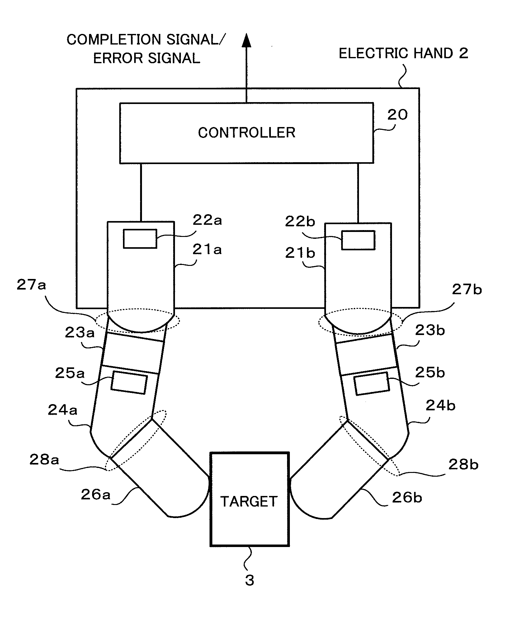
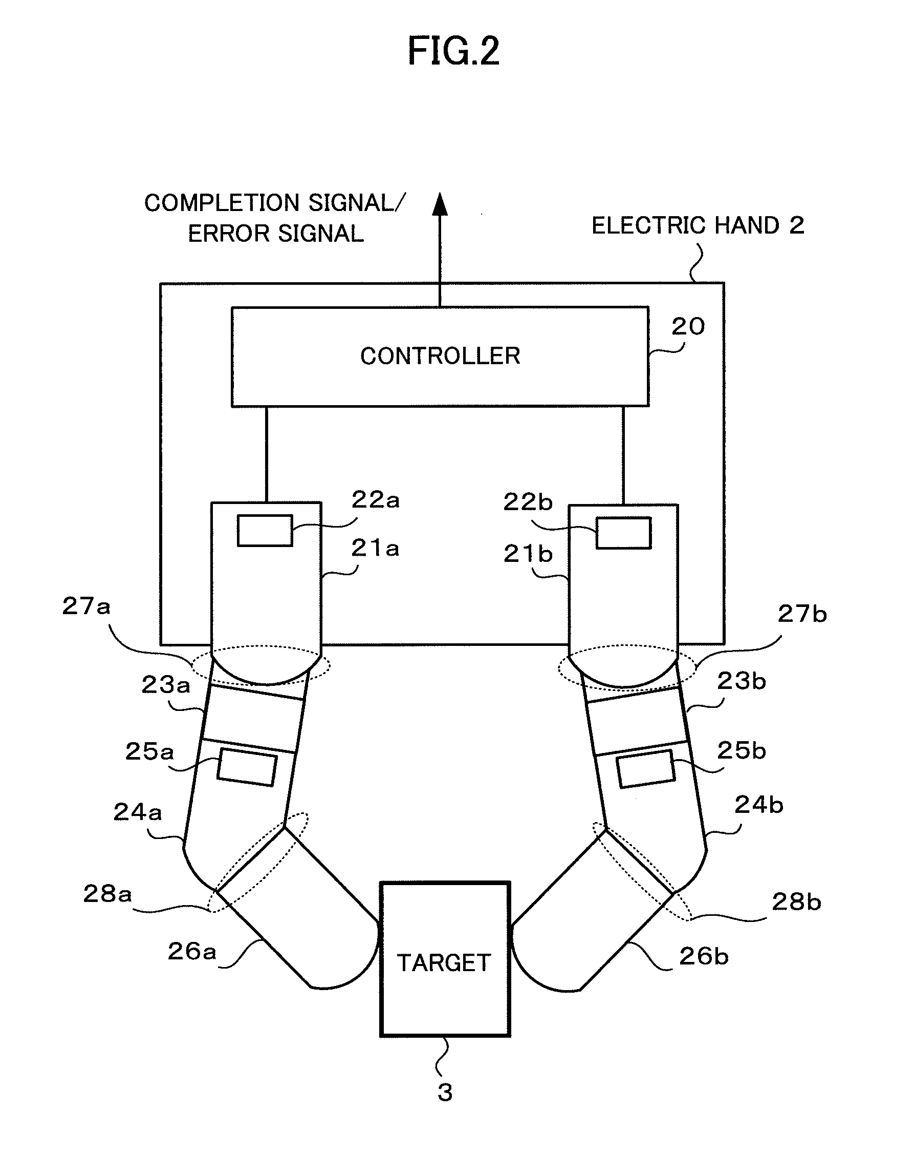
[0036]Next, an electric hand with a force sensor according to the present invention will be described with reference to FIG. 2.

[0037]An electric hand 2 includes two fingers (a first finger 26a and a second finger 26b). Each of the first and second fingers 26a and 26b includes two joints. That is, the first finger 26a includes a first joint 27a provided on the base portion side thereof and a second joint 28a provided on the front end side thereof. The second finger 26b includes a first joint 27b provided on the base portion side thereof and a second joint 28b provided on the front end side thereof.

[0038]The first joint 27a of the first finger 26a is rotated by a first actuator 21a, and the second joint 28a of the first finger 26a is rotated by a second actuator 24a. The first joint 27b of the second finger 26b is rotated by a first actuator 21b, and the second joint 28b of the second finger 26b is rotated by a second actuator 24b. In this way, the first and second joints 27a and 28a ...


PUM


Abstract

When a gripping instruction is issued, a position feedback control is performed so that an actuator of an electric hand is driven and a finger portion is moved toward a predetermined position target value. When the finger portion comes into contact with a target, the contact is determined by a force sensor. Then, the position feedback control is switched to a force feedback control, and the actuator is driven so that a force detection value obtained by the force sensor matches a predetermined force target value, so that the target may be gripped by an accurate gripping force.

Description

BACKGROUND OF THE INVENTION[0001]1. Field of the Invention[0002]The present invention relates to an electric hand that has a force sensor installed in a finger portion, and particularly, to an electric hand that has a finger portion opened and closed by an actuator so as to grip a target and has a force sensor installed in the finger portion so as to detect the gripping force.[0003]2. Description of the Related Art[0004]Basically, a robot is used to grip and carry a target, and a hand having a structure in which the target is sandwiched by a plurality of finger portions is generally used to grip the target. If the gripping force of the finger portion is too large when gripping the target by the finger portion, the target is crushed. Meanwhile, if the gripping force is too small, the target is dropped while the target is carried. For this reason, there has been a demand for a hand capable of appropriately adjusting the gripping force of the finger portion in response to the weight or...

Claims


Application Information

Patent Timeline
IPC IPC(8): B25J9/16B25J15/08B25J15/02
CPCB25J9/1612B25J15/0206Y10S901/32B25J15/08G05B2219/39322B25J13/082G05B2219/39532B25J9/1633
Inventor SAKANO, TESURO
Owner FANUC LTD
Why Eureka
Try Eureka