

Hand Dryer
a hand dryer and hand technology, applied in the field of hand dryers, can solve the problems of time-consuming and time-consuming process, affecting the quality of hand dryers, and affecting the quality of hand dryers, and achieve the effect of reducing the number of hands
- Summary
- Abstract
- Description
- Claims
- Application Information
AI Technical Summary
Benefits of technology
Problems solved by technology
Method used
Image


Examples
Embodiment Construction
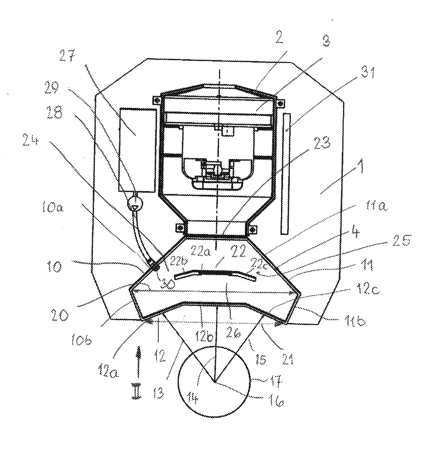
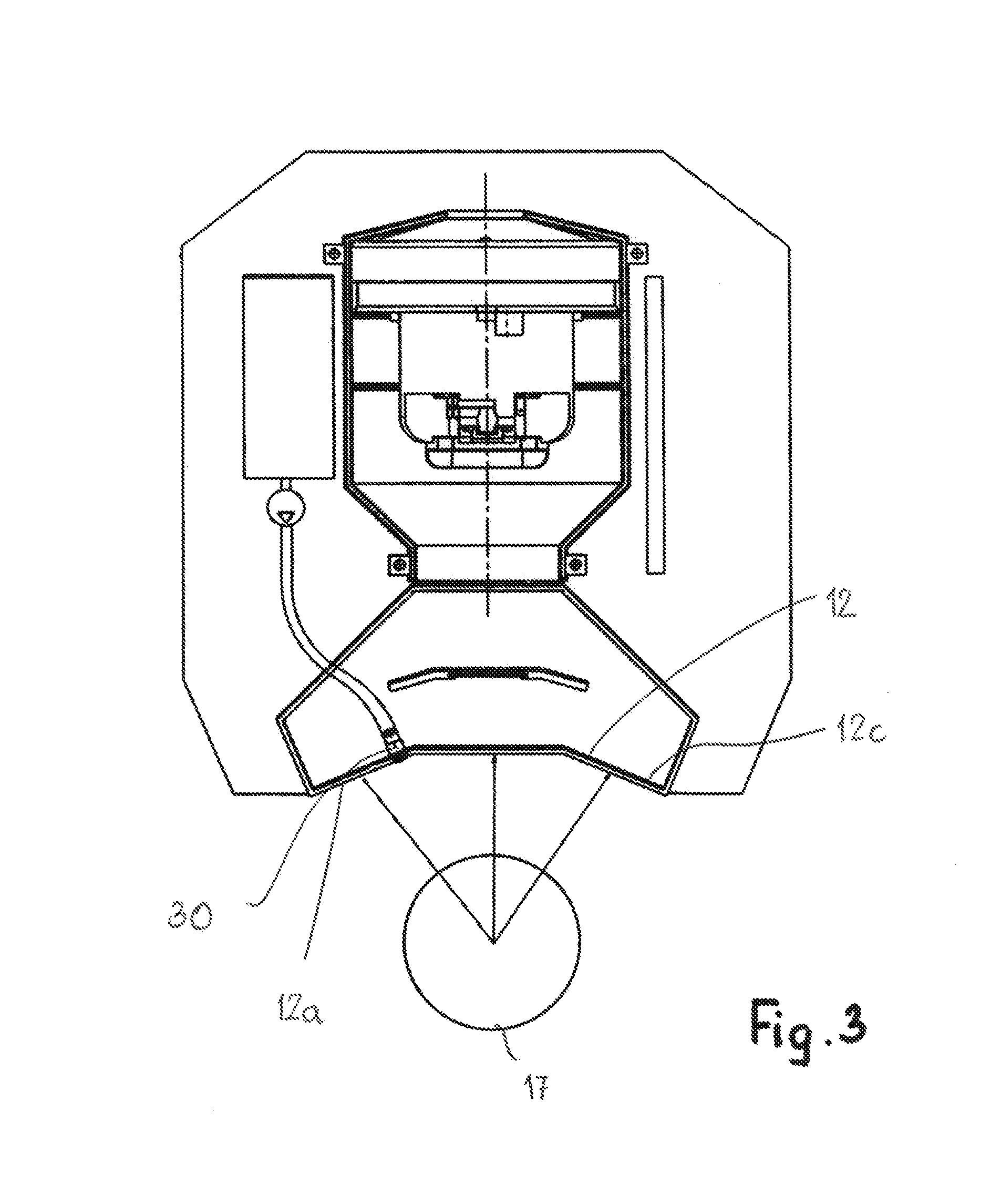
[0030]The hand dryer is designed such that it cannot only be used for drying but also for disinfecting the hands. The hand dryer is attached on a mounting plate 1, for example, that is fastened to a wall or the like, for example, by a screw connection. The hand dryer has a housing 2 in which a blower motor 3 is arranged with which, as is known in the art, an air stream is generated that exits at the bottom from the housing 2.
[0031]An air guide 4 is connected to the bottom end of the housing 2 and is provided with a rectangular cross-section (FIG. 2). The air guide 4 has three exit openings 5, 6, 7. They each have a circular cross-section and advantageously are of the same size.
[0032]The air guide 4 widens initially continuously away from the housing in the flow direction of the air. The air guide 4 has parallel longitudinal sidewalls 8, 9 that are connected to each other by narrow sidewalls 10, 11. The sidewalls 10, 11 are comprised of two wall sections 10a, 10b; 11a, 11b that are p...
PUM
 Abstract
Description
Claims
Application Information