Method for producing buttons, ornamental and instrument panels with fine symbols, and a button produced with the method

a technology of ornamental and instrument panels and buttons, applied in the direction of lamination, domestic objects, cabinet fitting arrangements, etc., can solve the problems of not being able to apply fine symbols defined on the button to metallic surfaces, unable to precisely position the interior symbol portion(s) of the button, and not being able to produce a button surface with this type of design

Active Publication Date: 2006-11-14
FAURECIA ANGELL DEMMEL
View PDF22 Cites 67 Cited by
  • Summary
  • Abstract
  • Description
  • Claims
  • Application Information

AI Technical Summary

Benefits of technology

[0015]It is therefore an aspect of the invention to improve a method and provide buttons, keys, as well as ornamental and instrument panels produced with this method, so that fine symbols can be applied to the button, which can optionally also be backlit, without the risk of having remaining portions of the plate material that are enclosed by cut-out symbols fall accidentally out of the plate.
[0026]If lamination takes place without a bonding agent (e.g., on open-pore support sheets), then the lamination foil can alternatively be printed. The step of coating the support plate is thereby eliminated.
[0033]The method has the advantage that the support plate can now be easily backlit and that the finely engraved function symbols, when illuminated, can be easily viewed with excellent edge definition.
[0035]Importantly, regions that are unattached following the engraving process need no longer be connected to the remaining surface of the support plate by webs or other connection means, because the unattached regions are already exactly positioned in the support plate and are fixedly connected with the support plate, thus eliminating the risk that these regions may fall out.

Problems solved by technology

It has not been possible until now to produce a button surface with this type of design.
The conventional method has the disadvantage that very fine symbols defined on the button could not be applied to metallic surfaces.
In addition, it proved difficult to precisely position the unattached interior symbol portion(s) which becomes even more difficult with narrower line widths.
The requirement to coordinate the visual effect with the surfaces of surrounding components also limits the use of alternative metallization methods.
However, a punching process is disadvantageously coarse.
In addition, burrs resulting from the punching process have to be tolerated since they are difficult to remove.
However, this exhibited the same disadvantages, name a relativity coarse cutting profile with undesirable cutting edges, burrs and support webs.
This has the disadvantage that the etched line width has to be always twice the material thickness, which prevents the application of fine symbols on a button.
However, the color and the appearance of the decor can only be adapted to the surrounding surfaces in a limited way.
In order to prevent the inner contour from being completely unattached, support webs have to be provided which can adversely affect the visual appearance of the inner contour and are therefore not acceptable for visual reasons.

Method used


Image

  • Method for producing buttons, ornamental and instrument panels with fine symbols, and a button produced with the method
  • Method for producing buttons, ornamental and instrument panels with fine symbols, and a button produced with the method
  • Method for producing buttons, ornamental and instrument panels with fine symbols, and a button produced with the method

Examples


Embodiment Construction

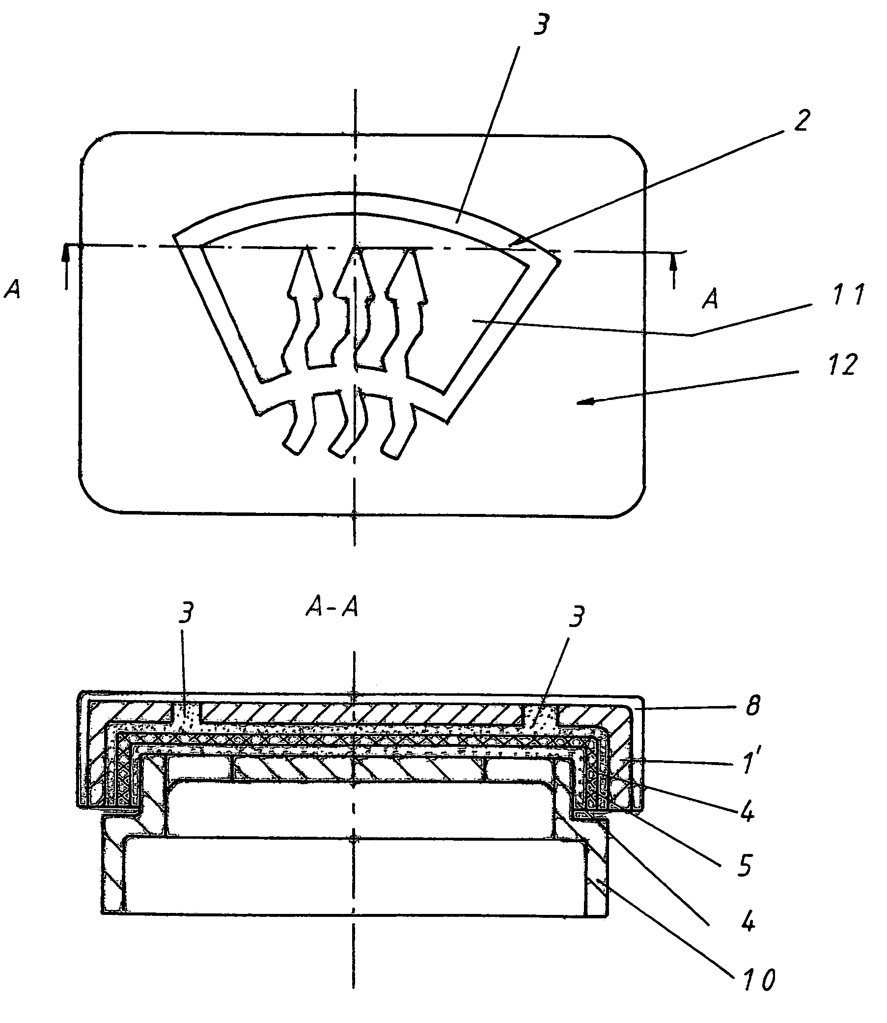
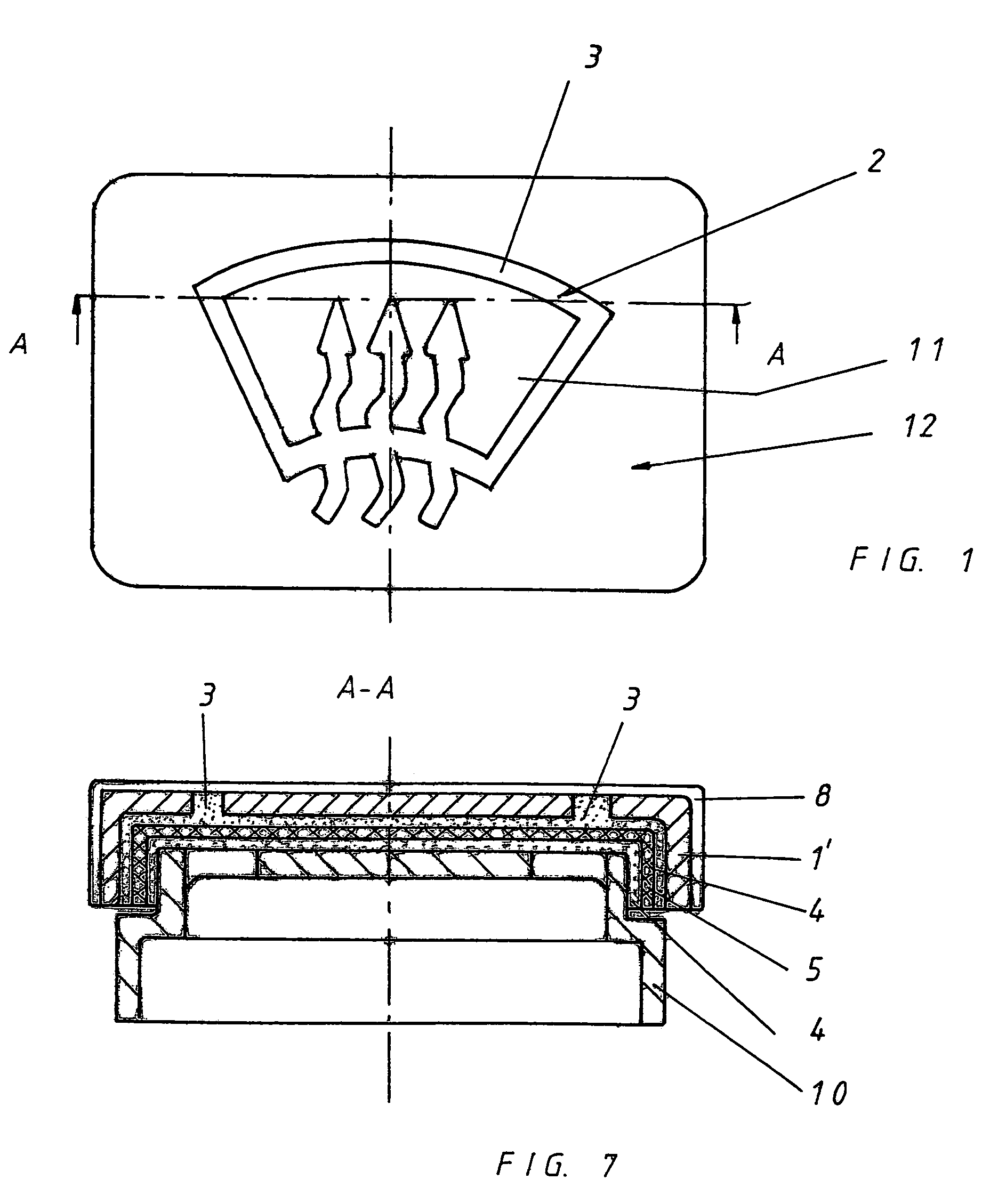
[0049]The button 12 is produced by first laser-engraving the backside of a support plate 1 which can have an arbitrary thickness. The support plate 1 in the present example is an aluminum sheet with a preferred sheet thickness between 0.2 and 0.5 mm.

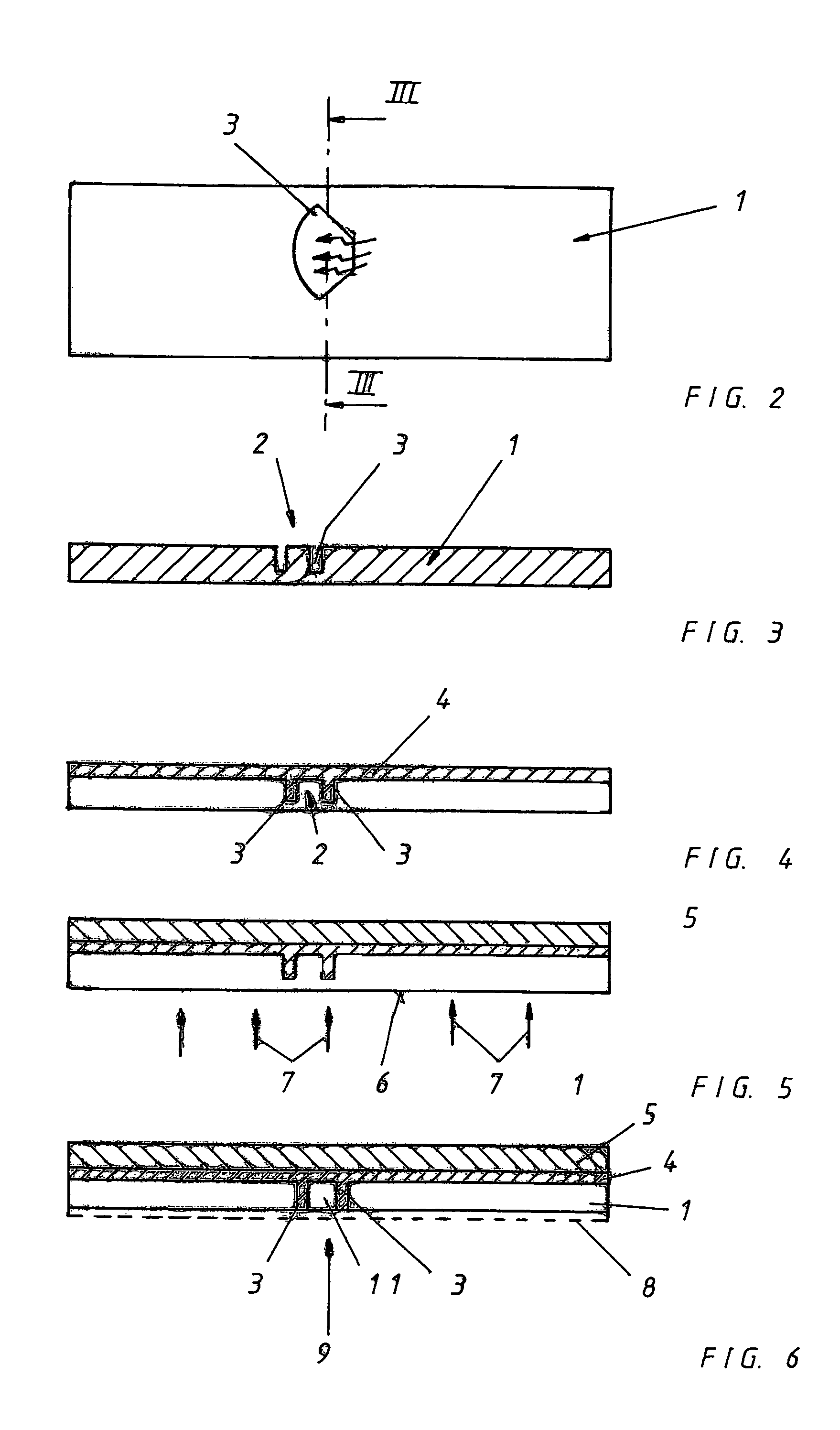
[0050]According to FIG. 2, the engraved line 3 for the function symbol 2 is transferred to the support plate 1 with a very fine line width (e.g., 0.15 mm line width for a 0.5 mm thick metal sheet).

[0051]However, the laser does not cut completely through the metal sheet, but only applies a deep engraving with a depth that leaves a residual wall thickness of approximately 0.01 mm in the support plate. This is shown in FIG. 3.

[0052]It is important to engrave the backside of the support plate 1, since all process-related surface blemishes (burr formation, burned material) are then located in the invisible area of the subsequently produced button.

[0053]Thereafter, the surface of the aluminum sheet is etched (by degreasing, pre-treatment for p...


PUM

PropertyMeasurementUnit
widthsaaaaaaaaaa
widthaaaaaaaaaa
thicknessaaaaaaaaaa

Abstract

A button, knob or control key with an etchable support plate which is engraved on the backside with a fine symbol by laser, erosion or mechanical engraving, which only cuts into the material of the support plate, but not through the support plate. The backside of the support plate is optionally coated. A foil is applied on the laminated layer and affixed thereto. The front side of the support plate is treated with a material-removing substance. The material removal with the material-removing substance is performed until the engraving extending into the support plate is at least partially or completely exposed on the front side. Application of a protective layer to the front side of the support plate from which the material was removed. A function symbol is provided on the button such that it can be backlit. It is engraved in a fine line width providing a sharp optical definition erosion, mechanical engraving.

Description

BACKGROUND OF THE INVENTION[0001]1. Field of the Invention[0002]The present invention relates to a method for producing buttons, control keys, ornamental and instrument panels with fine symbols and to a component produced with the method. The described buttons are often found in instrument panels of automobiles; however, buttons of this type can generally also be employed as control keys or buttons, for example, with electronic equipment.[0003]The following description describes the production of a button as one exemplary embodiment. However, this is not to be understood as a limitation, because the method can not only be used to process buttons and control keys, but also ornamental and instrument panels. The process of fabricating a button is described only to simplify the explanation, and the term button will hereinafter be used synonymously and interchangeably with control keys or other types of operating buttons, such as control knobs.[0004]2. Description of the Related Art[0005...

Claims


Application Information

Patent Timeline
Patent Type & Authority Patents(United States)
IPC IPC(8): B21D53/48B41J5/12H01H13/14B60K37/06H01H9/18H01H11/00
CPCH01H9/18H01H2009/187Y10T29/301Y10T29/30Y10T29/49986Y10T29/49599B29C45/1418B29C45/14811B32B37/18B32B37/24B32B38/10B32B2605/003
Inventor BRUENNEL, ELMAR
Owner FAURECIA ANGELL DEMMEL
Why Eureka
Try Eureka