Compressor bypass turbine-generator

a compressor bypass and turbine technology, applied in the direction of fluid couplings, rotary clutches, couplings, etc., can solve the problems of compressor degradation, degraded fuel economy, performance issues, etc., and achieve the effect of expanding the operating region of the engin

Active Publication Date: 2014-06-12
FORD GLOBAL TECH LLC
View PDF7 Cites 17 Cited by
  • Summary
  • Abstract
  • Description
  • Claims
  • Application Information

AI Technical Summary

Benefits of technology

[0002]Turbocharging an engine allows the engine to provide power similar to that of a larger displacement engine. Thus, turbocharging can extend the operating region of an engine. Turbochargers function by compressing intake air in a compressor via a turbine operated by exhaust gas flow. Under certain conditions, the flow rate and pressure ratio across the compressor can fluctuate to levels that may result in noise disturbances, and in more severe cases, performance issues and compressor degradation.

Problems solved by technology

Under certain conditions, the flow rate and pressure ratio across the compressor can fluctuate to levels that may result in noise disturbances, and in more severe cases, performance issues and compressor degradation.
However, the inventors herein have recognized that recirculation of compressed air may waste the energy utilized to the compress the air, leading to degraded fuel economy under some conditions.

Method used


Image

  • Compressor bypass turbine-generator
  • Compressor bypass turbine-generator
  • Compressor bypass turbine-generator

Examples


Embodiment Construction

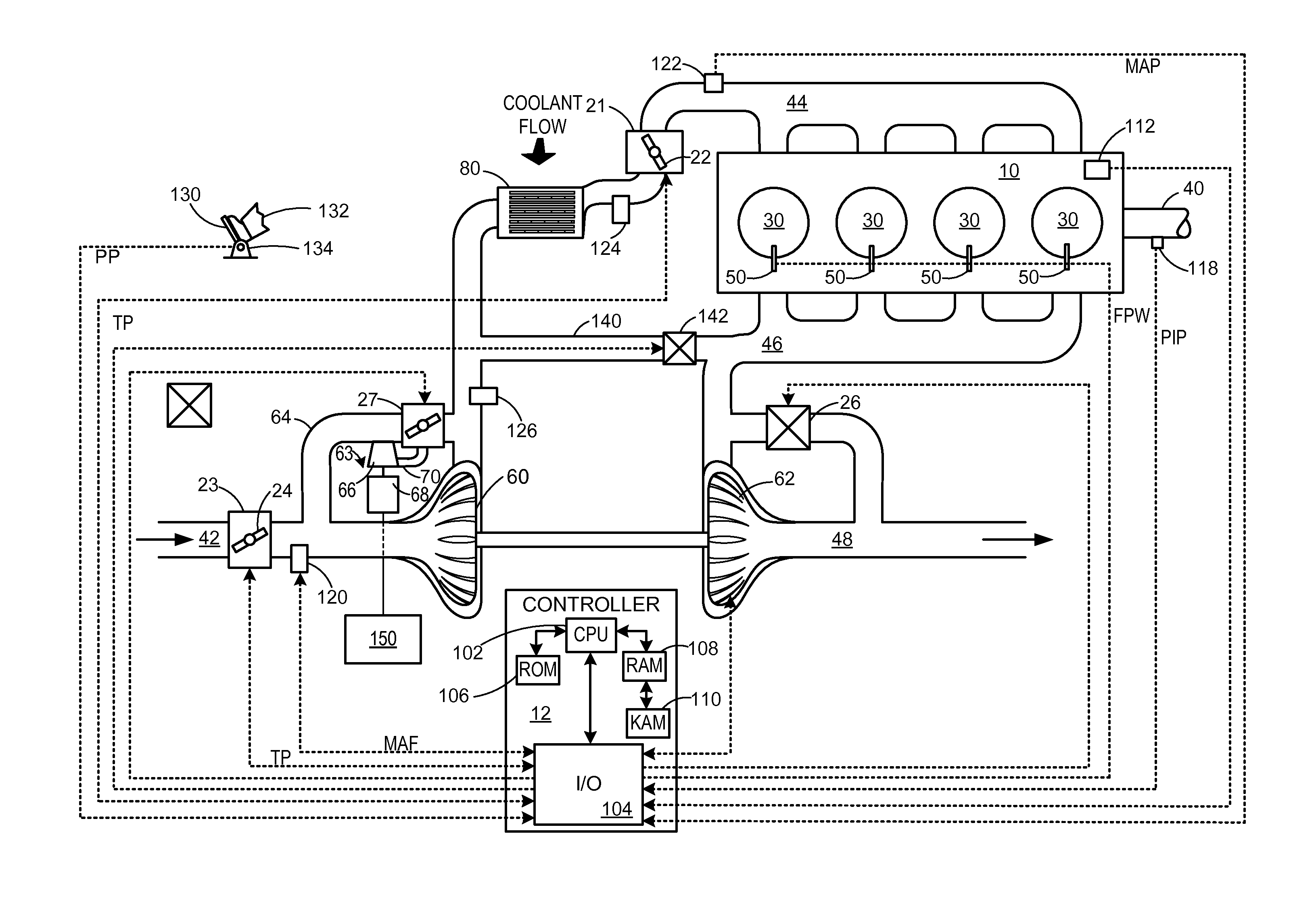
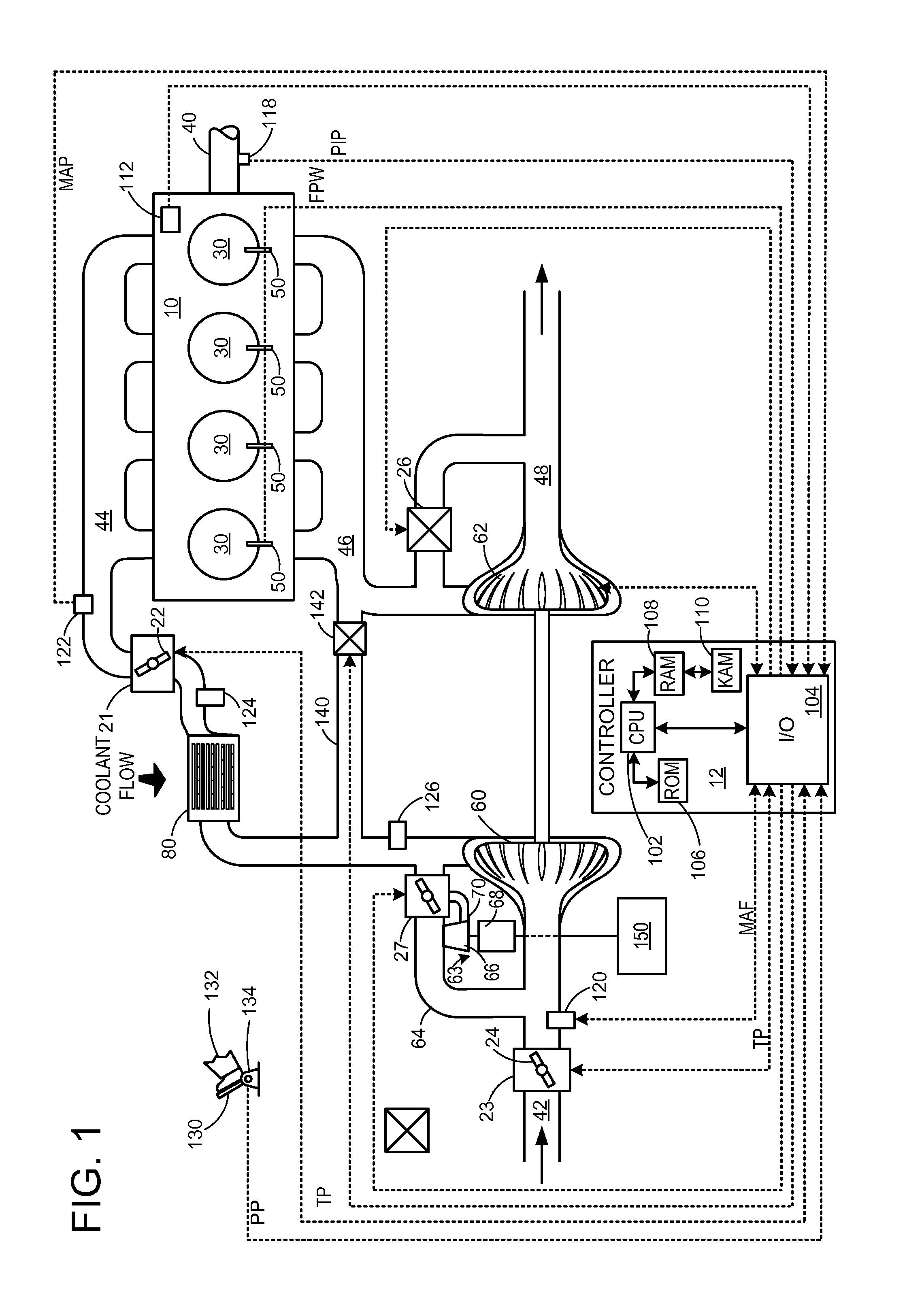
[0014]Compressor surge may occur when the pressure ratio across the compressor increases relative to the mass flow rate through the compressor. Compressor surge may result in noise disturbances, engine power fluctuations, and in some conditions, engine degradation. To control compressor surge, a compressor bypass valve may be opened to recirculate a portion of the compressed intake air to upstream of the compressor, thus increasing the flow through the compressor. A turbine may be positioned in the path of the compressor bypass flow. The turbine may be coupled to an energy conversion device such as a generator. In this way, when the compressor bypass valve is opened, the recirculated air may be passed through the turbine to generate energy in the energy conversion device.

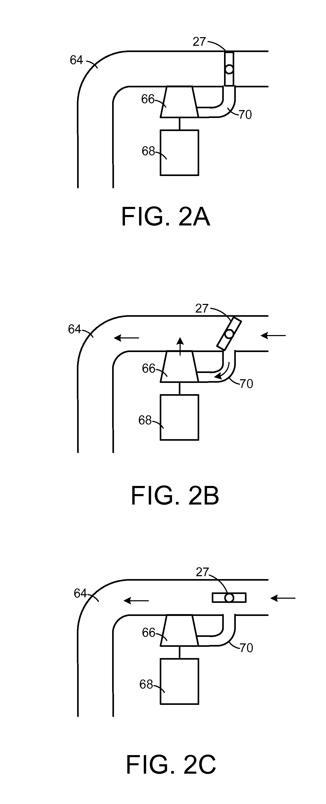
[0015]An engine system including a compressor, compressor bypass valve, and turbine-generator is illustrated in FIG. 1. The compressor bypass valve may be adjusted to multiple positions, illustrated in FIGS. 2A-3C. ...


PUM


Abstract

Embodiments for a turbine-generator position in a compressor bypass flow path are presented. In one example, a method for an engine having a compressor comprises generating energy via a turbine-generator positioned in a bypass flow path of the compressor. In this way, the energy of the recirculated intake air may be recovered by the turbine-generator.

Description

FIELD[0001]The present disclosure relates to an internal combustion engine.BACKGROUND AND SUMMARY[0002]Turbocharging an engine allows the engine to provide power similar to that of a larger displacement engine. Thus, turbocharging can extend the operating region of an engine. Turbochargers function by compressing intake air in a compressor via a turbine operated by exhaust gas flow. Under certain conditions, the flow rate and pressure ratio across the compressor can fluctuate to levels that may result in noise disturbances, and in more severe cases, performance issues and compressor degradation.[0003]Such compressor surge may be mitigated by one or more compressor bypass valves (CBV) located in the intake. The CBVs may recirculate compressed air from the compressor outlet to the compressor inlet. However, the inventors herein have recognized that recirculation of compressed air may waste the energy utilized to the compress the air, leading to degraded fuel economy under some conditi...

Claims


Application Information

Patent Timeline
Patent Type & Authority Applications(United States)
IPC IPC(8): F02B37/16
CPCF02B37/164Y02T10/12
Inventor MCCONVILLE, GREGORY PATRICKMACERONI, KAREN ELIZABETH
Owner FORD GLOBAL TECH LLC
Why Eureka
Try Eureka