Apparatus for analysing a small amount of liquid

Active Publication Date: 2014-06-12
HELLMA
View PDF4 Cites 10 Cited by
  • Summary
  • Abstract
  • Description
  • Claims
  • Application Information

AI Technical Summary

Benefits of technology

[0029]Suitably both said deflectors are integrated simultaneously in a lid which can be placed on the sample holder from above, so that for example by turning the lid through a constructionally defined angular dimension about its rotation axis, simple s

Problems solved by technology

It has however been found in particular that on fluorescence measurements, due to the direct deflection of the excitation light in the direction of the detector by means of the detachably mountable reflector, the detector is over-irradiated with too great a quantity of light.
As a result the detector can become saturated and sometimes damaged.
At least the exciting radiation cannot be distinguished from the fluorescent radiation, which is subst

Method used


Image

  • Apparatus for analysing a small amount of liquid
  • Apparatus for analysing a small amount of liquid
  • Apparatus for analysing a small amount of liquid

Examples


Example

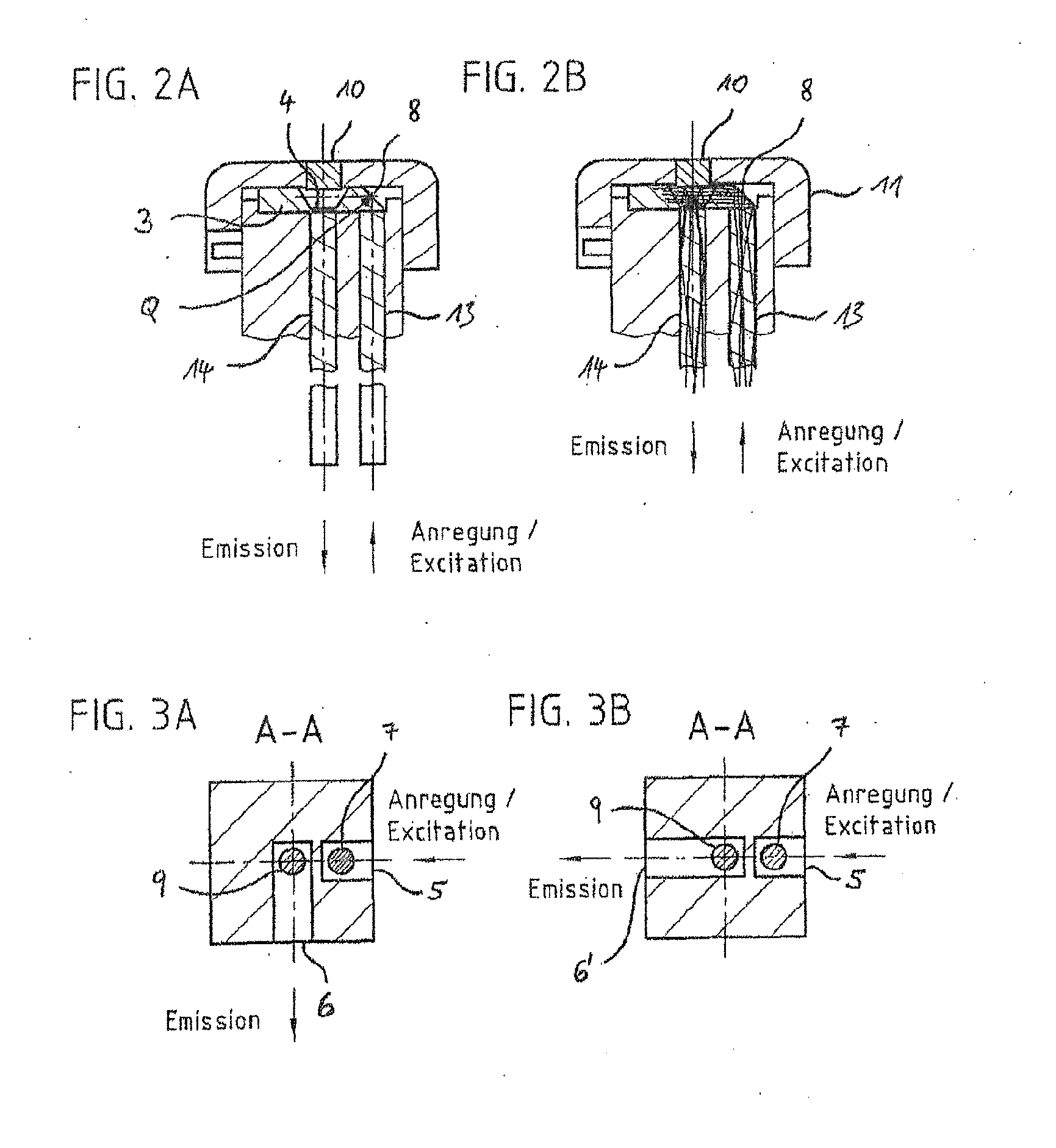
[0054]FIGS. 4A and 4B show a second embodiment of the analysis apparatus according to the invention which can be used both to measure fluorescence and to measure the absorption properties of the liquid sample P in the sample receiving point 4. FIG. 4A shows a detailed view of the upper part of the analysis apparatus 100 in which the second light deflection is achieved by two optical deflector elements 108 and 118 which can be used alternatively. The one deflector element is designed as an externally reflecting prism 108, which is mounted on the side and below the lid 111 of the apparatus 100 such that with its base 108a it is arranged above the light guide 113 for the excitation light and deflects the excitation light beam by 90° in order to introduce it horizontally into the sample in the sample receiver 4. In contrast to the first embodiment, here the sample holder 103 does not extend right into the region above the light guide 113 for the excitation light, but the light emerges f...

Example

[0057]As already shown in the first embodiment in FIGS. 3A and 3B, in the embodiment in FIGS. 4A and 4B too, the light outlet opening can be arranged at 90° to the light incident opening in the housing of the analysis apparatus 1 (FIG. 5A), wherein the apparatus 100 can then be inserted in conventional fluorescence meters. Alternatively the light outlet opening 6′ can also be arranged at 180°, i.e. aligned with the light inlet opening on the opposite side of the housing of the apparatus 100, so that measurements of fluorescence / luminescence (FIG. 4A) and absorption (FIG. 4B) can be carried out in a photometer or spectrophotometer (FIG. 5B).

Example

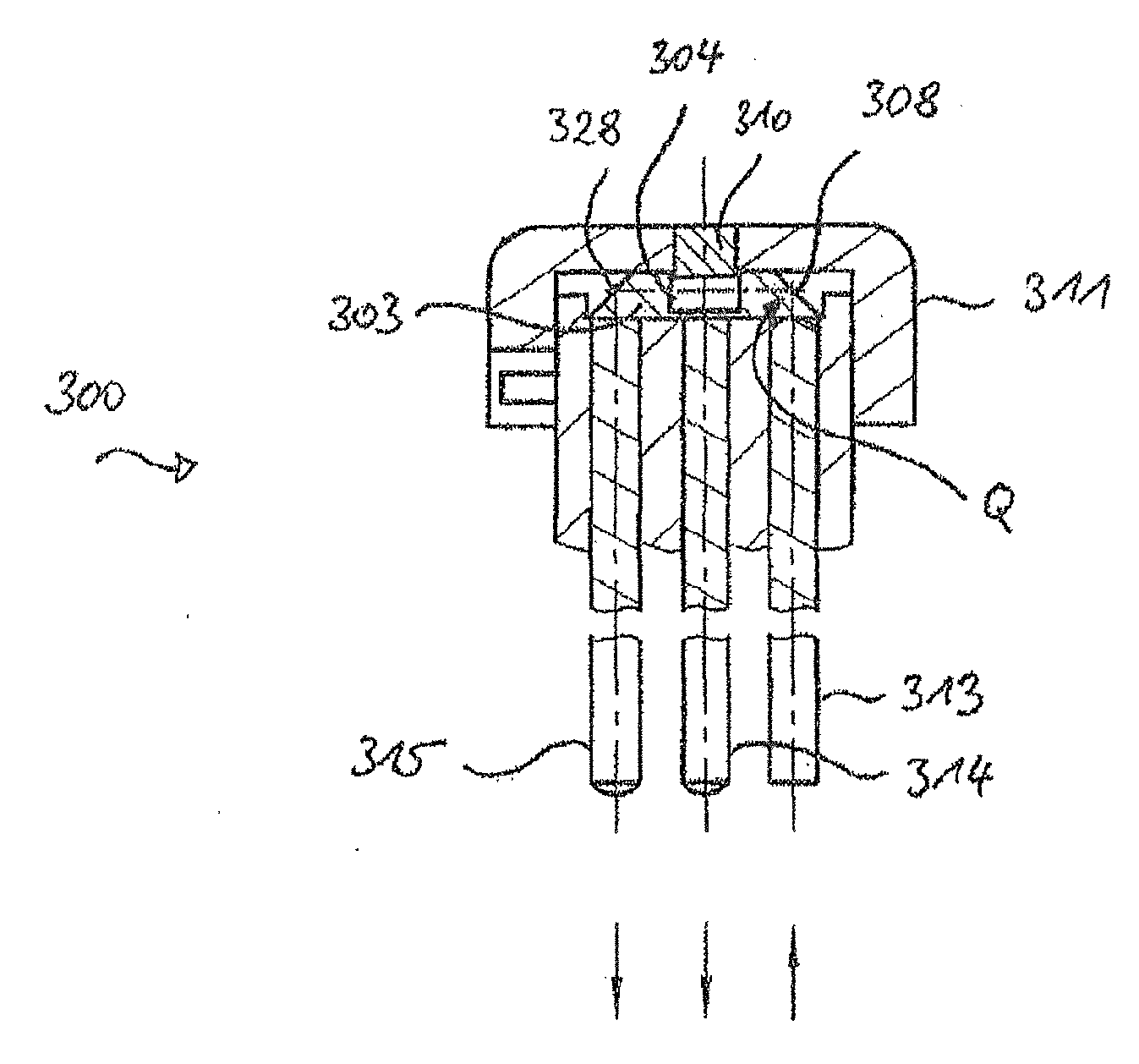
[0058]FIGS. 6A to 6C show a third embodiment of the present invention. It should be noted now that FIGS. 6A and 6B again—like FIGS. 1A and 1B—show section views rotated by 90°. In this embodiment the analysis apparatus 200—like the first and second embodiments—comprises a light guide 213 which guides the excitation light from the first light deflector 207 next to the sample receiver 4. Above the sample holder 203 and arranged eccentrically is a frustoconical prism 218 which, as a second light deflector like that in the second embodiment, deflects the excitation light so that it is conducted vertically into the sample receiver 4 and transmitted through the sample P. Accordingly a light guide 214 is again provided along the vertical axis of the apparatus 200 and (as in the operating mode in FIG. 4B of the second embodiment) guides the transmitted light carrying the absorption signature vertically downward. There it is deflected into the horizontal by a second detector-side light defle...


PUM


Abstract

An apparatus (1) for analysing, measuring the fluorescence, luminescence, phosphorescence, Raman scattering or absorption of a small amount, for example a drop, of a liquid sample (2) with the aid of light (3) which can be guided through the sample (2) and can then be detected or analysed according to said measuring methods. Said apparatus comprises a sample holder which is at the top when in the position of use and has a receiving point (4) for applying or dripping the sample (2), and a light inlet (5) for excitation light, said light inlet being horizontally oriented when in the position of use and below the sample holder (4). The apparatus has a first device (7) which is downstream of the light inlet (5) in the beam path and is used to deflect the light upwards to a position to the side of the receiving point (4), and second light deflection means (8) which guide the light beam coming from the bottom into the sample to be analysed.

Description

INTRODUCTION[0001]The invention concerns an apparatus for analysing, measuring the fluorescence, luminescence, phosphorescence, Raman scattering or absorption of a small amount, for example a drop, of a liquid sample using light which is guided through the sample and can then be detected or analysed according to said measurement methods, wherein the apparatus has an upper receiving point which is flat in the working position, for application or dripping of the sample, a light inlet which is oriented horizontally in the working position in its housing below the receiving point, and a first device arranged downstream of the light inlet in the beam path to deflect the light upwards to the receiving point, and a second light deflector which deflects the light beam coming from below into the sample to be analysed.PRIOR ART[0002]A similar apparatus is described in German patent DE 10 2004 023 178 B4 and has proved useful in practice as a universal accessory for absorption measurement. It ...

Claims


Application Information

Patent Timeline
IPC IPC(8): G01N21/64G01N21/59G01N21/65
CPCG01N21/64G01N21/65G01N21/59G01N21/0303G01N21/645G01N2021/035
Inventor SAHIRI, THOMASGREIFFENREICH, STEFANIEKANDLER, HOLMKOLTUNSKI, CHRISTOF
Owner HELLMA
Why Eureka
Try Eureka