Analysis and Compensation Circuit for an Inductive Displacement Sensor

Active Publication Date: 2009-12-10
KNORR-BREMSE SYST FUER NUTZFAHRZEUGE GMBH
View PDF9 Cites 23 Cited by
  • Summary
  • Abstract
  • Description
  • Claims
  • Application Information

AI Technical Summary

Benefits of technology

[0007]The invention is therefore based on the object of providing a circuit arrangement for evaluation and compensation of signals from an inductive position sensor, which is insensitive to external magnetic alternating fields and produces an electrical signal with better accuracy and good dynamics.
[0026]On the one hand, the invention is therefore based on the idea of providing a first circuit part for the position or frequency measurement, in which a measurement coil which acts in an RLC series resonant circuit is used to measure and produce a suitable output signal, and on the other hand additionally on the use of a second circuit part, which uses a resistance measurement to allow temperature compensation and compensation for inaccuracies, induced by external magnetic disturbance fields, in the temperature compensation of the measurement coil, and which therefore allows even better measurement accuracy. Both of the abovementioned circuit parts are largely insensitive to temperature fluctuations and interference from external magnetic fields, therefore in particular reducing the sensitivity of the circuit to magnetic disturbance fields.

Problems solved by technology

However, it is complex to measure the coil internal resistance, because of the low resistance of the plunger-type coil.
Furthermore, if the measurement is carried out as a DC voltage measurement, this results in disadvantages in terms of susceptibility to external magnetic alternating fields and DC voltage shifts within the circuit arrangement that is used, for example as a result of an input voltage shift in an operational amplifier, which result in the position measurement not being sufficiently accurate.
Both of the abovementioned circuit parts are largely insensitive to temperature fluctuations and interference from external magnetic fields, therefore in particular reducing the sensitivity of the circuit to magnetic disturbance fields.

Method used


Image

  • Analysis and Compensation Circuit for an Inductive Displacement Sensor
  • Analysis and Compensation Circuit for an Inductive Displacement Sensor
  • Analysis and Compensation Circuit for an Inductive Displacement Sensor

Examples


Embodiment Construction

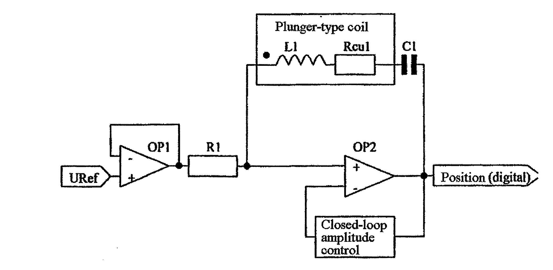
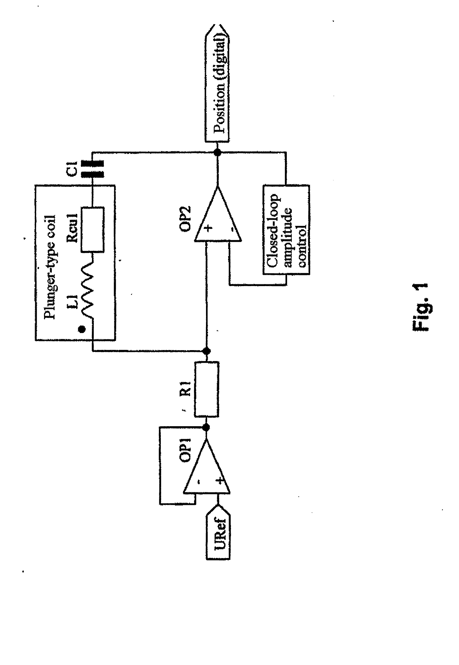
[0030]In detail, FIG. 1 shows an outline circuit of the preferred position sensor system for position measurement, without the temperature or magnetic disturbance fields of the plunger-type coil or sensor coil being detected for compensation purposes, showing a first operational amplifier OP1, which is used as an inverting amplifier with its output signal being fed back to a first of its inputs (−) and to a second input (+) at which a reference voltage Uref is supplied, and whose output is connected to a resistor R1.

[0031]The output voltage from the resistor R1 is supplied to a first input (+) of a second operational amplifier OP2, whose output signal is fed back via suitable circuitry for closed-loop amplitude control to a second of its inputs (−). The closed-loop amplitude control in this case ensures that the resonant circuit oscillates reliably in every operating state, and that the oscillation frequency remains stable.

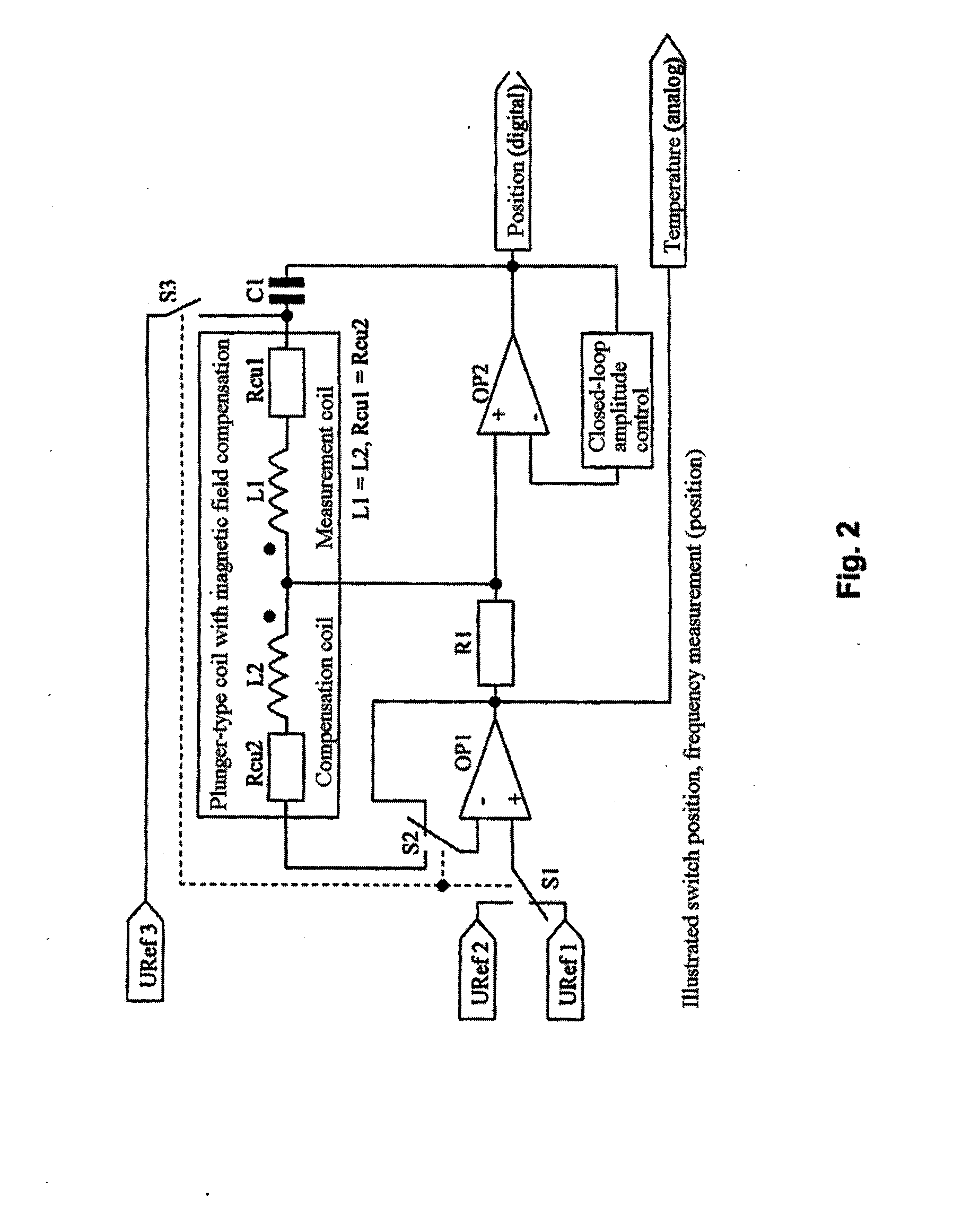
[0032]Furthermore, the sensor coil which is used for positio...


PUM


Abstract

A circuit arrangement for analysis and compensation of the signals for an inductive displacement sensor is provided. The circuit includes a first operating amplifier, a second operating amplifier and a coil for a displacement measurement, in parallel with the second operating amplifier output and the second operating amplifier first input and connected to a capacitance in series with the coil inductance and coil resistance to form an RLC series tuned circuit. In order to improve the accuracy of a measured resonance frequency, the circuit arrangement can be extended with a second coil for a temperature compensation, by connecting a first of the ends of the coil winding to a second end of the coil winding of the first coil and a second of the ends of the coil winding to the second input of the first operating amplifier.

Description

CROSS-REFERENCE TO RELATED APPLICATIONS[0001]This application is a U.S. National Phase of PCT International Application No. PCT / EP2006 / 012439, filed on Dec. 22, 2006, which claims priority under 35 U.S.C. §119 to German Application No. 10 2005 062 906.7, filed Dec. 29, 2005, the entire disclosures of which are expressly incorporated by reference herein.BACKGROUND AND SUMMARY OF THE INVENTION[0002]The invention relates to a circuit arrangement for evaluation and compensation of the signals from an inductive position sensor, for example as is used in vehicle braking systems.[0003]Pneumatic cylinders are frequently provided in braking systems such as these, with pistons whose piston position can be detected without contact being made, over a wide operating temperature range, generally from −40° C. to +150° C., in all operating states, for example in the presence of oil mist.[0004]In known solutions which are used for these purposes, a plunger-type coil is generally used as a sensor coi...

Claims


Application Information

Patent Timeline
IPC IPC(8): G01R27/26
CPCG01D5/2013G01D5/22G01D5/202
Inventor FEUCHT, THOMASGSCHEIDLE, WOLFGANG
Owner KNORR-BREMSE SYST FUER NUTZFAHRZEUGE GMBH
Why Eureka
Try Eureka