Surveillance system

a surveillance system and camera technology, applied in the field of surveillance systems, can solve the problems of insufficient resolution to distinguish objects at 30 metres or more, end resolution is ultimately limited, optical resolution requires a more expensive image sensor,

a surveillance system and camera technology, applied in the field of surveillance systems, can solve the problems of insufficient resolution to distinguish objects at 30 metres or more, end resolution is ultimately limited, optical resolution requires a more expensive image sensor,

US20140160294A1Active Publication Date: 2014-06-12GARRETT THERMAL SYST LTD +1

Image

  • Surveillance system
  • Surveillance system
  • Surveillance system

Examples


Embodiment Construction

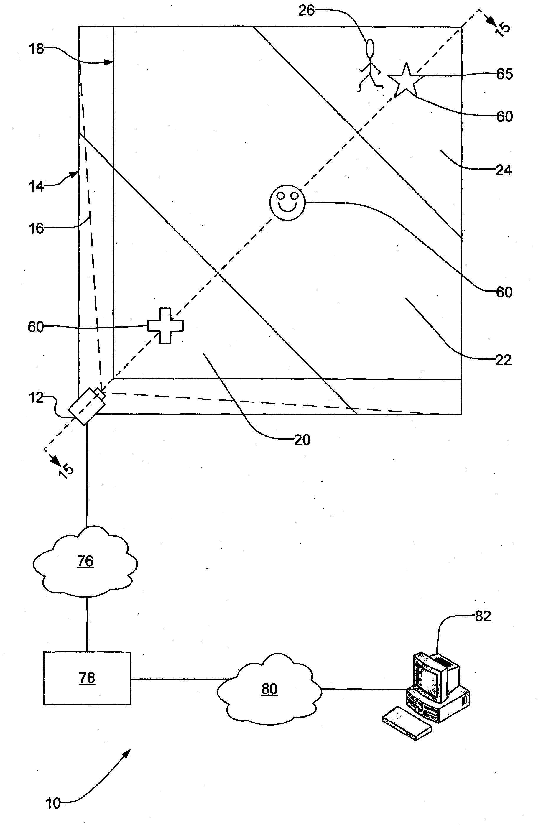
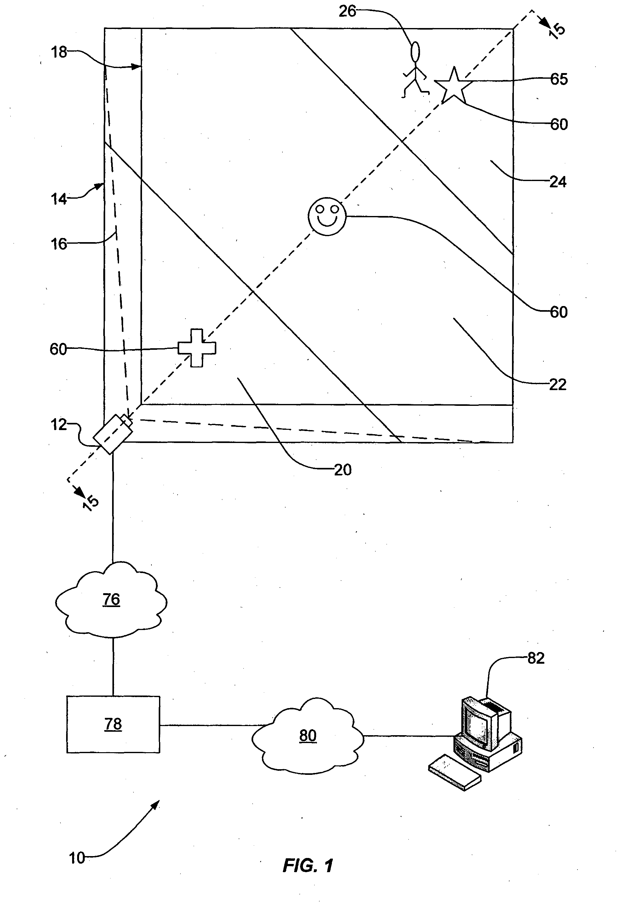
[0051]A surveillance system that is in accordance with an embodiment of the present invention is shown in FIG. 1. Surveillance system 10 has an image capturing system which in this embodiment is an imaging device in the form of a camera 12. The camera 12 is installed at a site 14 with boundary fence or wall fence 13, for the purpose of monitoring activity within the site. The camera has a field of view 16 for monitoring a region of interest 18 within the site 14. This is depicted in plan view in FIG. 1. The region includes a plurality of zones including a zone in the near field 20, a zone in the mid field 22 and a zone in the far field 24.

[0052]In the presently described embodiment, the camera is installed above ground at a corner location to monitor for an intruder 26 in the region of interest 18. The camera 12 captures a sequence, at predetermined intervals, of images of the field of view 16 containing the region of interest 18. The images may be used to determine whether an intru...


PUM


Abstract

A surveillance system (10) for monitoring movement in a region of interest (18) is described. The surveillance system (10) includes: An image capturing system (12) having a field of view (16) including a region of interest (18), and adapted to capture an image of the region of interest (18). An image processing system (78) configured to process a time-sequential series of images of the field of view from the image capturing system such that at least a portion (52, 53, 54) of each processed image (50) is analysed for detecting movement within the region of interest (18). The image capturing system (12) is configured to capture, in each image, different apparent magnifications of respective zones (20, 22, 24) within the region of interest (18) in the field of view (16) that are at different distances from the image capturing system (12) such that an object (60) in at least one position in at least two of said zones has substantially the same apparent size in the images.

Description

FIELD OF THE INVENTION[0001]The present invention relates to methods and systems for surveillance. In one aspect, the invention relates to the use of cameras in surveillance.BACKGROUND OF THE INVENTION[0002]Video Motion Detection (VMD) may be used for surveillance applications such as for perimeter protection and intrusion detection. It uses a computer to analyse a video sequence of the perimeter of a property, and provides notification which may include an alarm, if an intruder appears in the scene. Typically, such a system will operate in the near field, covering an area from a few metres in front of the camera to 30 metres away. The image has enough resolution to readily distinguish subjects in the near field, and barely sufficient resolution to distinguish objects at 30 metres or more.[0003]To resolve objects that are further away, higher resolution cameras may be used to capture an image at a higher optical resolution. While the resolution of an image may be improved by softwar...

Claims


Application Information

Patent Timeline
12 Jun 2014
Publication
US20140160294A1
IPC
G08B13/196
CPC
G08B13/19606; G08B13/1961; H04N7/18; G08B13/19602
Inventors
NAYLOR, MATTHEW JOHN