Golf Club

Active Publication Date: 2014-06-12
CENTLINE GOLF CLUBS
View PDF10 Cites 4 Cited by
  • Summary
  • Abstract
  • Description
  • Claims
  • Application Information

AI Technical Summary

Benefits of technology

[0067]These clubs may not conform to PGA rules for club design. Manufacturers have made club heads larger

Problems solved by technology

The long shaft of a fairway wood also requires lots of room to swing, making it unsuitable for tighter lies such as “punching” out from underneath tr

Method used


Image

  • Golf Club
  • Golf Club
  • Golf Club

Examples


Embodiment Construction

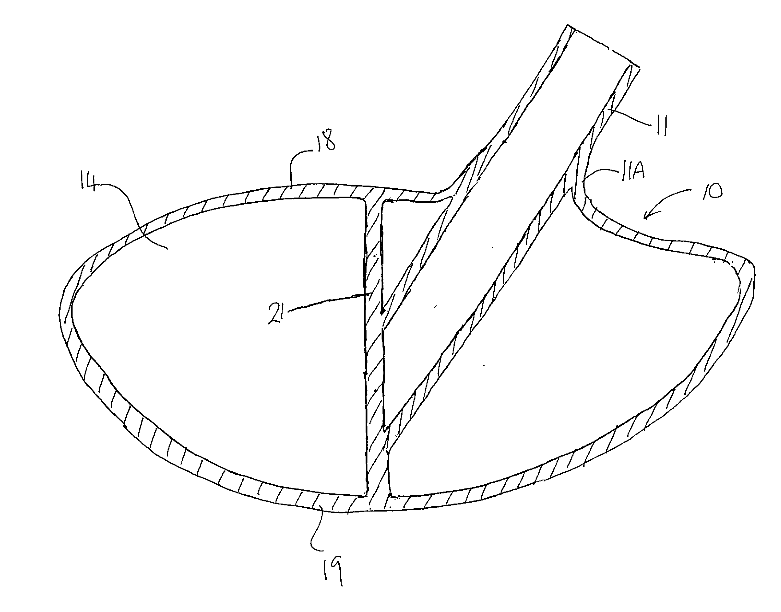
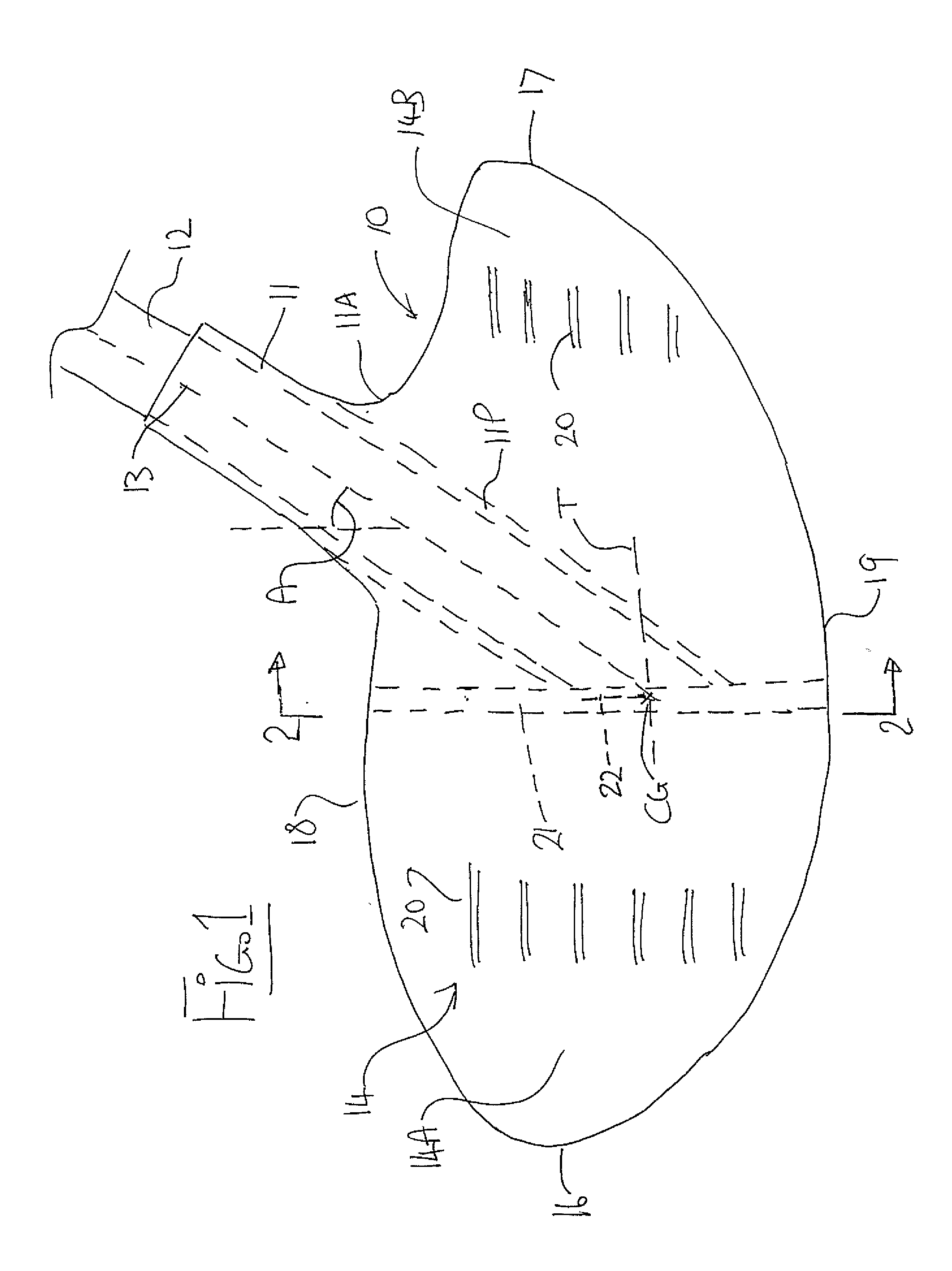
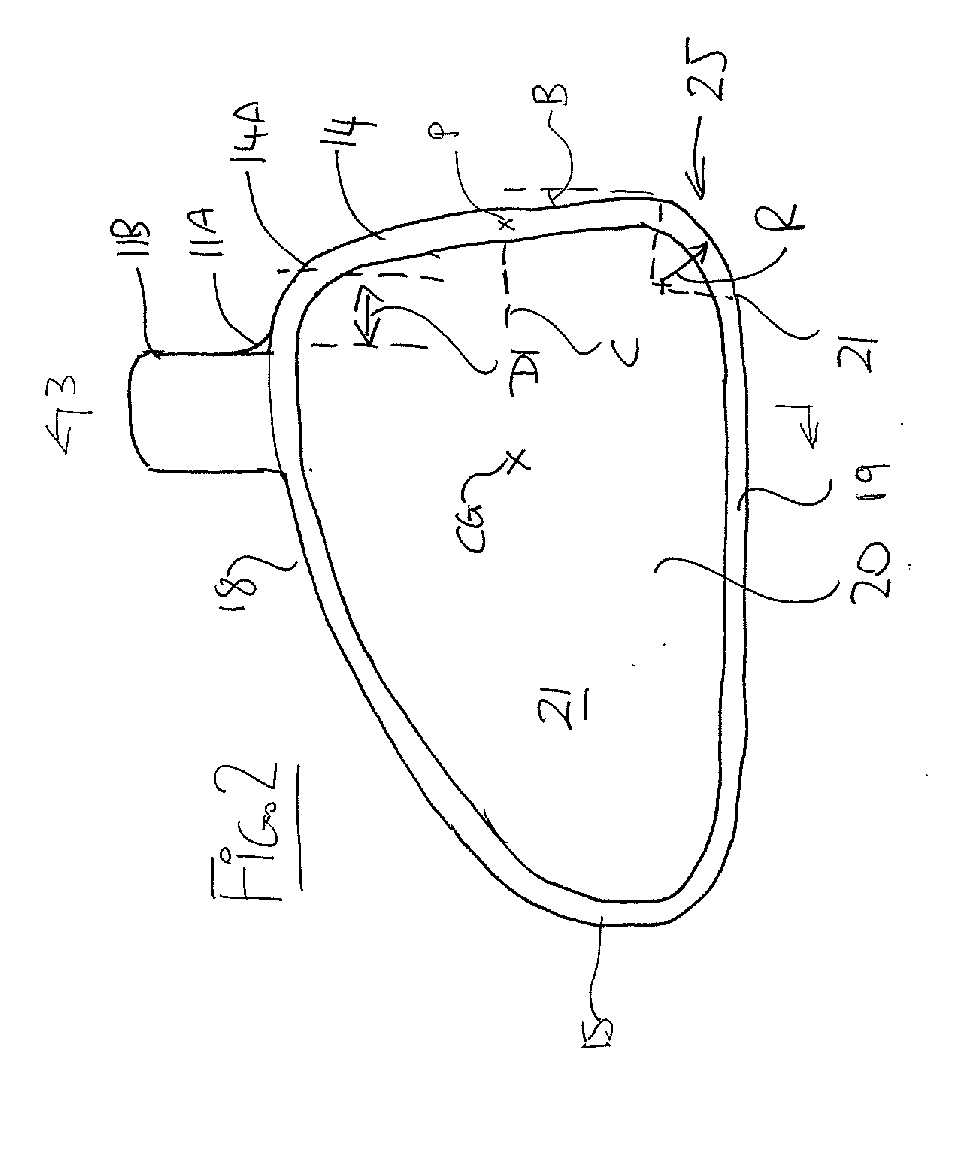
[0076]In FIGS. 1 and 2 is shown a golf club having a club head 10, a hosel 11 and a shaft 12. The shaft 12 has a center line 13. The hosel is a tubular body having a center line which is coincident with the center line 13 so that the shaft extends into the hosel and its centre line continues along the center line of the hosel.

[0077]The club head 10 forms forming a generally hollow body having a generally planar front wall 14 for impacting a ball, a rear wall 15 opposite to the front wall, two side walls 16, 17, a top wall 18 and a bottom wall 19 surrounding a hollow interior 20.

[0078]The hosel is arranged on the club head so that the shaft extends at an angle A less than ninety degrees to a transverse line which angle is arranged so that the club is intended to be swung in driving action of a driver or iron to cause impact. The front wall lies in a plane at an angle B to a vertical plane so as to provide a loft angle for driving the ball during impact.

[0079]An upstanding center wall...


PUM


Abstract

A golf club has a club head forming a generally hollow body having a generally planar front wall for impacting a ball, a rear wall opposite to the front wall, two side walls, a top wall and a bottom wall surrounding a hollow interior. A tubular shaft hosel extends upwardly from the top wall of the club head and an upstanding center wall is located between the side walls and extending rearwardly from the front wall so as to transfer forces between walls. A portion of the hosel is connected to the top wall and the center wall so as to transfer forces therebetween. The front edge of the center wall can be recessed away from the front wall to allow some flexing of the front wall on impact.

Description

CROSS-REFERENCE TO RELATED APPLICATIONS[0001]This application claims the benefit under 35 USC 119(e) of U.S. Provisional Application Ser. No. 61 / 668,532 filed Jul. 6, 2012 and of U.S. Provisional Application Ser. No. 61 / 733,157 filed Dec. 4, 2012, the contents of which are incorporated herein by reference.FIELD OF THE INVENTION[0002]This invention relates to an improved golf club.BACKGROUND OF THE INVENTION[0003]The present invention relates to golf clubs of the wood or hybrid type where the club is formed as a hollow body including front, rear, top, bottom and side walls surrounding a hollow interior.[0004]For clarity it is pointed out that a wood is a type of club which have longer shafts and larger, rounder heads than other club types, and are used to hit the ball longer distances than other types.[0005]Woods are so called because, traditionally, they had a club head that was made from hardwood, generally persimmon, but modern clubs have heads made from metal, for example titaniu...

Claims


Application Information

Patent Timeline
IPC IPC(8): A63B53/04A63B53/02
CPCA63B53/02A63B53/047A63B53/0466A63B53/0454A63B53/045A63B53/0408A63B60/00
Inventor TOUCHETTE, SHANE M.
Owner CENTLINE GOLF CLUBS
Why Eureka
Try Eureka