Morphologically curved sagittal wall of a tibial implant

a tibial implant and sagittal wall technology, applied in the field of tibial implant morphologically curved sagittal wall, can solve the problems of insufficient anterior-posterior stability the most optimal design of the straight walled implant, and the inability to maintain constant resection depth, so as to achieve greater anterior-posterior stability and optimize placement

Active Publication Date: 2015-12-10
MAKO SURGICAL CORP
View PDF5 Cites 0 Cited by
  • Summary
  • Abstract
  • Description
  • Claims
  • Application Information

AI Technical Summary

Benefits of technology

[0003]Tibial implants having a curved sagittal wall portion taking into account both general anatomic features of the proximal tibia as well as providing greater anterior-posterior stability than implants having a straight sagittal wall portion are

Problems solved by technology

However, a straight walled implant may not be the most optimal design to retain constant resection depth on both sides of the eminence and to avoid ligaments b

Method used


Image

  • Morphologically curved sagittal wall of a tibial implant
  • Morphologically curved sagittal wall of a tibial implant
  • Morphologically curved sagittal wall of a tibial implant

Examples


Embodiment Construction

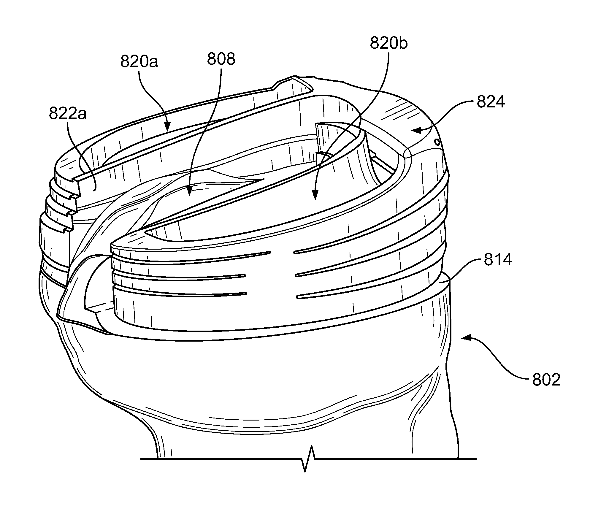
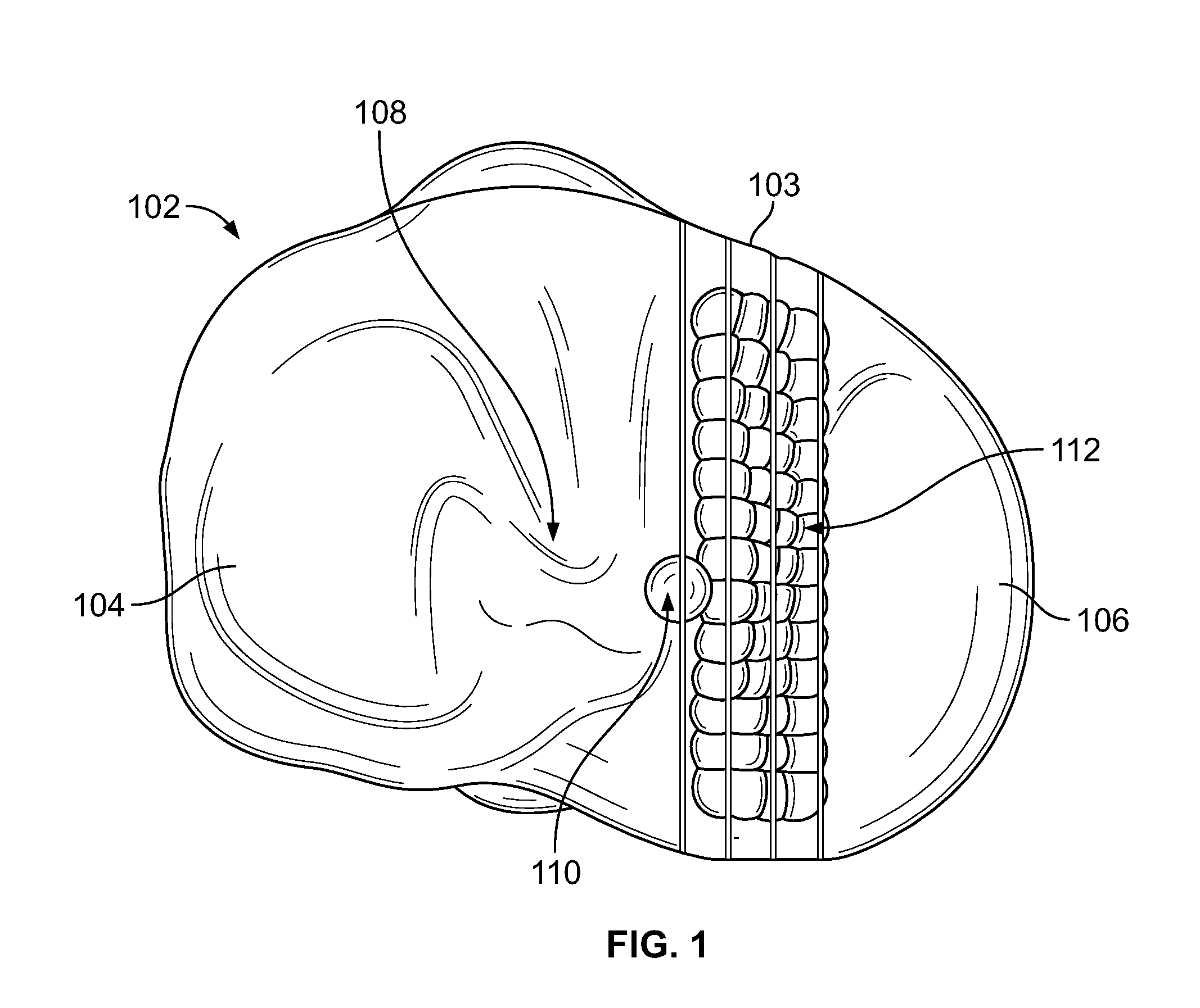
[0028]Referring to the drawings, wherein like reference numerals represent like elements, there is shown in the figures, in accordance with embodiments of the present invention, prosthetic implants and virtual bone models. FIGS. 1-4 illustrate one method of designing a prosthetic implant for fabrication having a curved sagittal wall using a virtual bone model 102. In this embodiment, the method includes obtaining or generating at least one virtual bone model 102. Bone model 102 is a bone model of a proximal tibia having lateral 104 and medial 106 portions or sides. The lateral 104 and medial 106 sides are separated by a tibial eminence 108.

[0029]A high point 110 is identified on bone model 102 representing a location on the bone model that is the greatest linear distance away from a proposed resection plane 114 measured about a longitudinal axis of bone model 102. In the present embodiment, high point 110 corresponds to the high point of the medial tibial spine of bone model 102 of ...


PUM


Abstract

Disclosed herein are methods of designing and fabricating prosthetic implants having a sagittal wall in which at least a portion thereof traverses a non-linear path. A method of fabricating such a prosthetic implant may include generating a virtual bone model based on image information obtained from at least one bone, determining a proposed height of the prosthetic implant at a first location on the virtual bone model, determining a proposed resection depth into the at least one bone at the first location based at least in part on the proposed height of the prosthetic implant, and determining a curved resection path across a portion of the virtual bone model. The curved resection path may intersect the first location and the prosthetic implant may have a curved sagittal wall corresponding to the curved resection path.

Description

BACKGROUND OF THE INVENTION[0001]Current knee arthroplasty tibial implants that retain the tibial eminence contain a straight sagittal wall portion which banks against the eminence. Typically, the sagittal wall resection of the eminence corresponding to the straight sagittal wall of an implant is made with a reciprocating saw normal to the transverse tibial resection plane. When placing an eminence-preserving implant, preferences to component placement on a cut plane include avoiding ligaments, optimizing bony coverage, avoiding deep cuts into the eminence, and permitting possible kinematic trialing feedback, for example.[0002]However, a straight walled implant may not be the most optimal design to retain constant resection depth on both sides of the eminence and to avoid ligaments because the native eminence wall itself is not a perfectly straight line. A straight walled implant also may not provide sufficient anterior-posterior stability.SUMMARY OF THE INVENTION[0003]Tibial implan...

Claims


Application Information

Patent Timeline
IPC IPC(8): A61B19/00G06F19/00A61F2/38
CPCA61B19/50A61F2230/0063G06F19/3437A61F2/389A61F2002/30112A61F2002/3895A61B34/10G16H50/50
Inventor DAVIGNON, ROBERTFERKO, MICHAEL C.AXELSON, JR., STUART L.
Owner MAKO SURGICAL CORP
Why Eureka
Try Eureka