Method and apparatus for treating sewage

Active Publication Date: 2014-06-19
ANTONIO DE ASMUNDIS FULVIO +1
View PDF6 Cites 5 Cited by
  • Summary
  • Abstract
  • Description
  • Claims
  • Application Information

AI Technical Summary

Benefits of technology

[0016]A further main object of the invention consists of providing a method and apparatus for treating sewage which enable to effectively eliminate the majority of microorganisms, such as bacteria, moulds, mould spores and bacteria present in the sewage.
[0017]It is a further object of the invention to provide a metho

Problems solved by technology

De facto, the wastewater treatment by means of chemical additives make the method expensive and difficult to control.
Specifically, the treatment by means of chemical additives is hardly manageable under conditions wherein it is necessary to treat wastewater having different concentrations of dissolved substances: in this ca

Method used


Image

  • Method and apparatus for treating sewage
  • Method and apparatus for treating sewage
  • Method and apparatus for treating sewage

Examples


fifth embodiment

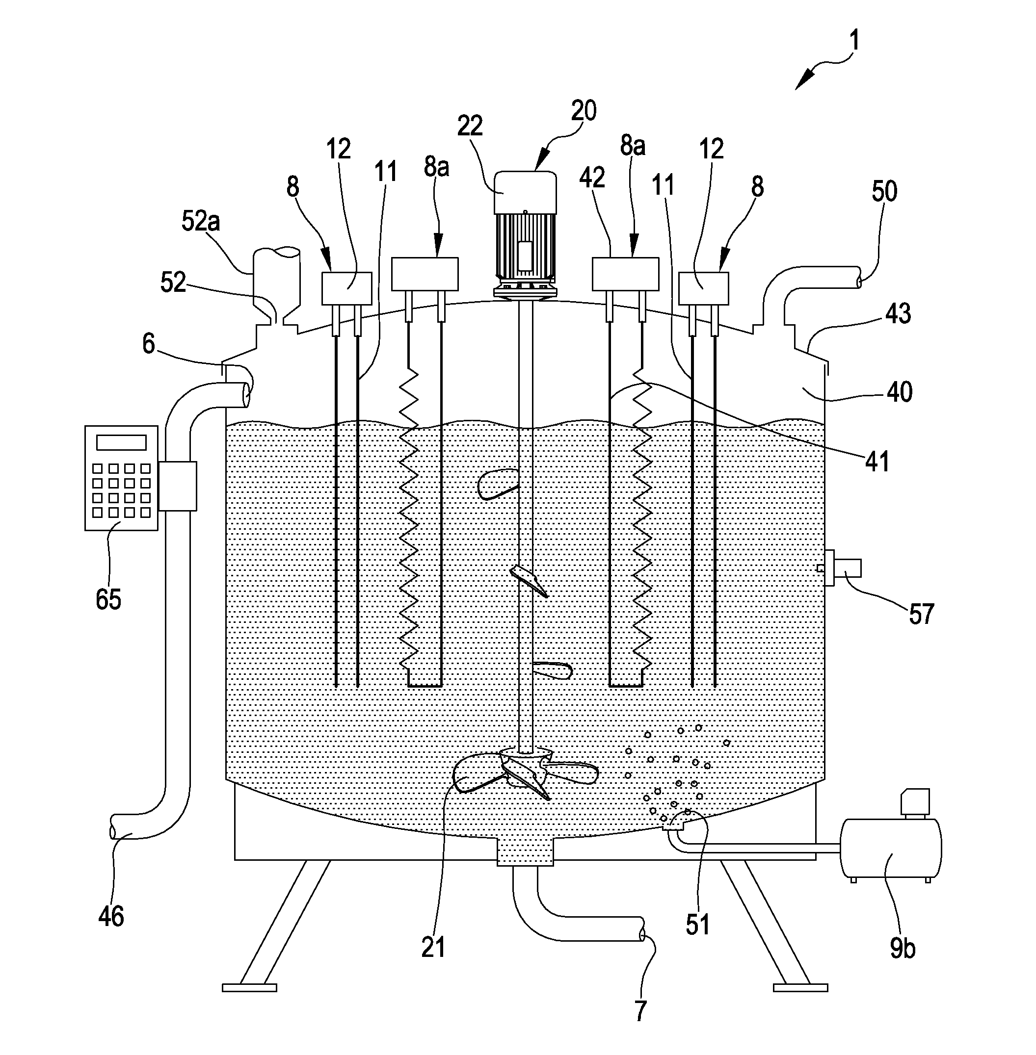
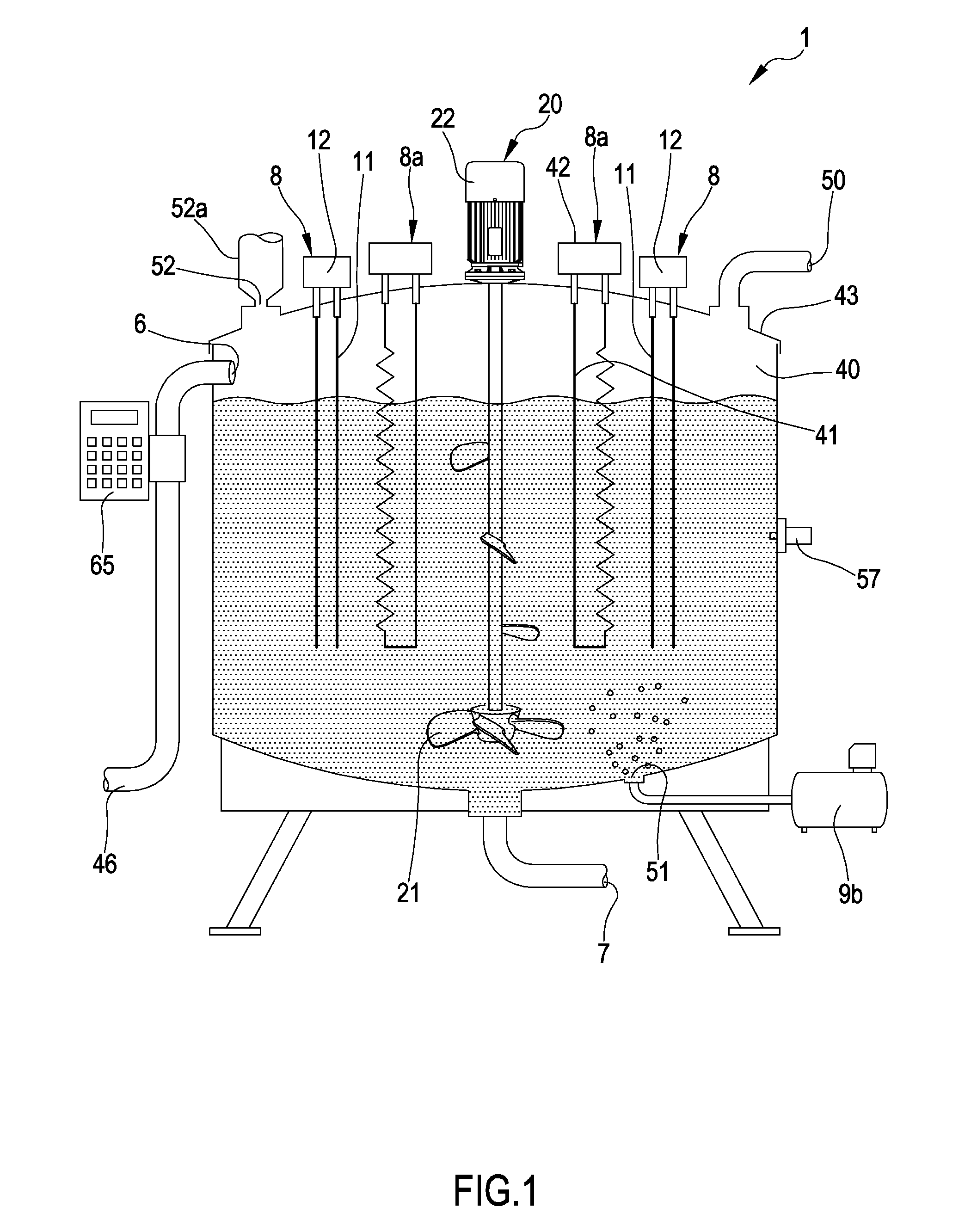
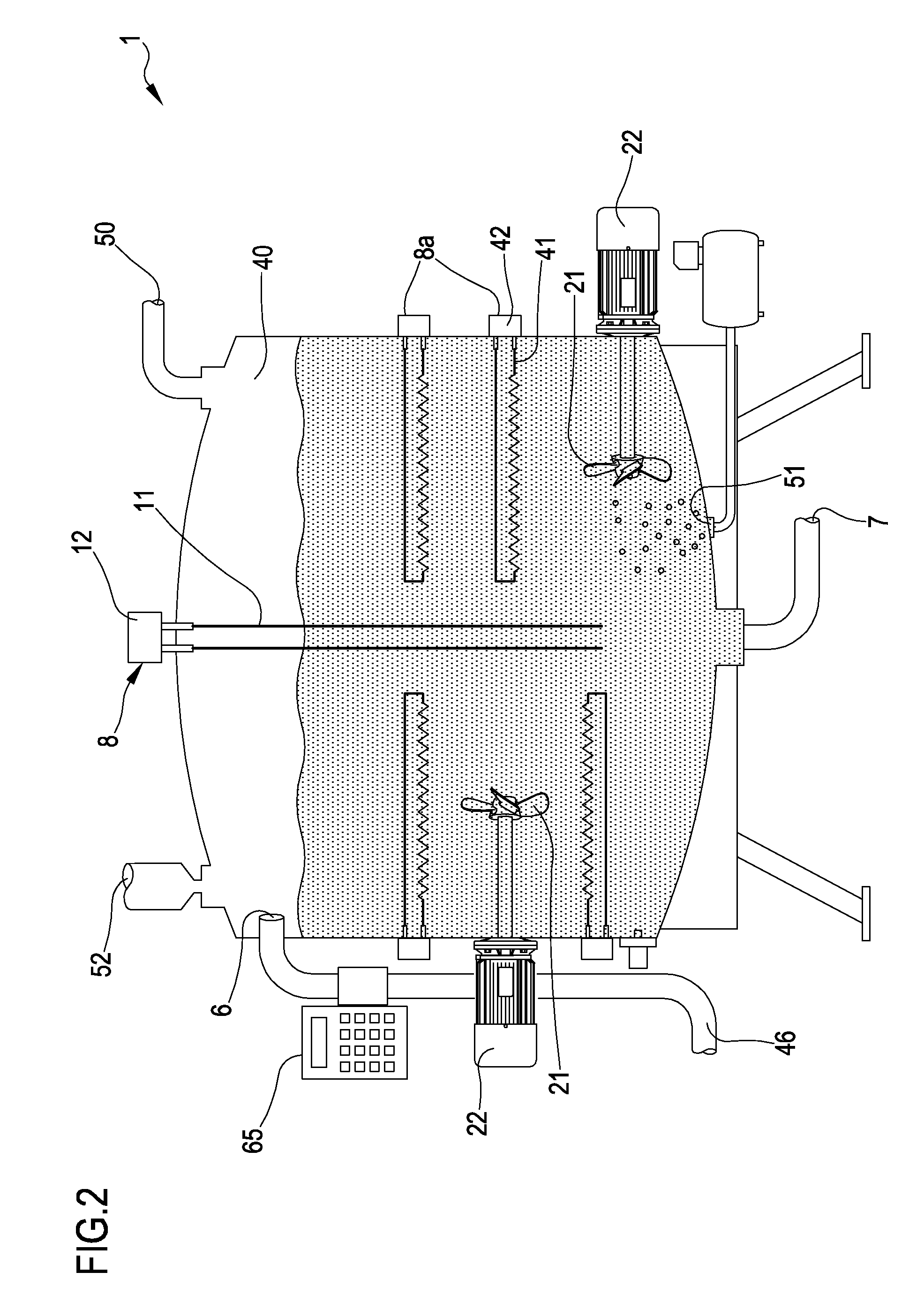
[0291]In the fifth embodiment, first tank 5 comprises, below the inlet 6, a sloped support 70 configured to receive the sewage fed through inlet 6. Support 70 comprises, in a non limiting way, a plate having main extension direction and extending between a first end 71, constrained to tank 5, and a second end 72 suspended inside first tank 5 at a level lower than the level at which first end 71 is positioned. The level difference (slope) of the plate enables sewage from inlet 6 to flow on the latter to second end 72.

[0292]A pair of electrodes 11 of an electrolytic cell 8 is engaged on the plate: sewage flowing on plate is energised by the electrolytic cell 8 which in turn promotes the dissociation from sewage of gases comprising nitrogen.

[0293]In the embodiment of FIG. 4a, blowing device 9b is positioned at second end 72 of plate and particularly below the latter. First inlet 51 of device 9b is positioned in the direction of sewage falling from the second plate end: the air and / or n...

first embodiment

[0362]The pressure increase of the gas flow ascending towards the upper zone is mainly caused by the choke defined by the recovery plate 38 which substantially reduces the gas cross-section. FIG. 7 schematically shows third tank 32 having a supply conduit for the gases recovered in first and second tanks, merging at the top of second tank 32, and substantially extends at the bottom wall of the latter, where it defines gas inlet 33.

[0363]In the embodiment of FIG. 7, the recovery plate has an arched body having a concavity facing the lower zone 32b of third tank.

[0364]In an embodiment variant of third tank 32 shown in FIG. 7A, third tank has a conduit supplying gases, directly leading to the bottom wall (the passage of the conduit inside the tank itself is absent) on which it is defined the gas inlet 33.

[0365]Inside solution A, in a non limiting way, it is arranged a series of intercepting elements 73 configured to define a zigzag path. The gas, introduced from inlet 33, ascends towar...


PUM

PropertyMeasurementUnit
Fractionaaaaaaaaaa
Lengthaaaaaaaaaa
Lengthaaaaaaaaaa

Abstract

Apparatus for sewage treatment, comprising: at least one tank (13), at least one inlet branch (14) to the tank (13), at least one outlet branch (15) from the tank (13), at least one microwave generator (9a) able to subject the sewage present internally of the tank (13) to at least one temperature raising treatment, at least a cooling circuit (19) of the microwave generator (9a), at least one blowing device (9b) connected to the tank (13). Blowing device (9b) is connected to an outlet (26) of the cooling circuit (19) and sending the heated gases arriving therefrom into the tank (13).

Description

FIELD OF THE INVENTION[0001]The present invention relates to a method and apparatus for treating sewage.[0002]The apparatus and method, object of the invention, find application in the zootechnical field for managing and exploiting sewage and / or waste of animal origin.[0003]Moreover, the present invention can find an application in the field of wastewater treatment coming from: agricultural systems, food farming industry, waste management systems, systems for producing power from biogas, residential water (foul water) treatment systems.TECHNICAL BACKGROUND[0004]It is known, in the industrial and agricultural fields, the use of apparatus and methods for treating wastewater and sludge comprising sewage in order to dispose of the undesired substances, in order to reduce the toxicity and purify such water and / or sludge in order to enable a correct recovery or disposal.[0005]Particularly, methods and apparatus for treating residential and / or industrial wastewater using chemical, mechanic...

Claims


Application Information

Patent Timeline
IPC IPC(8): C02F1/30B01J19/12C02F1/461
CPCC02F1/02C02F1/36C02F1/461C02F1/4672C02F1/4676C02F1/74C02F1/78C02F2103/20C02F2201/46155C02F2201/4619C02F2209/001C02F1/302Y02W30/40Y02E50/30B01J19/126C02F1/46104B01D19/0078H05B6/80
Inventor ANTONIO, DE ASMUNDIS FULVIO
Owner ANTONIO DE ASMUNDIS FULVIO
Why Eureka
Try Eureka