
Feed forward signal cancellation

a technology of forward signal and cancellation, applied in the field of full-duplex wireless communication system, can solve problems such as system ineffective reception of desired signals, and achieve the effect of reducing self-interference signals

Inactive Publication Date: 2014-06-19
KUMU NETWORKS
View PDF13 Cites 162 Cited by
  • Summary
  • Abstract
  • Description
  • Claims
  • Application Information

AI Technical Summary

Benefits of technology

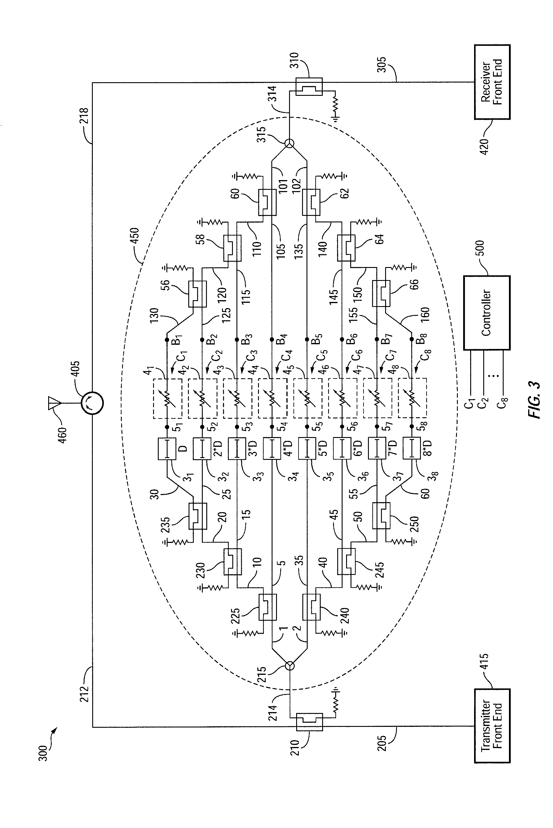
The present invention is related to a circuit and method for reducing self-interference in a communication system. The circuit includes a first signal path and a second signal path, each containing a delay element and a variable attenuator. The first and second signal paths are designed to receive a sample of a transmit signal and generate a delayed and weighted sample of the transmit signal. The first and second groups of P and M signals are associated with each other and are designed to form P / 2+M / 2+1 associated time windows. The method includes delivering a first portion of the transmit signal to a first passive coupler to generate a first signal portion, delivering a second portion of the transmit signal to a second passive coupler to generate a second signal portion, and combining the first and second signals to generate a combined signal representative of the self-interference signal. The method also includes setting the delay of the first and second signals to fall within the associated time windows and determining the weights of the signals based on the intersections of an estimate of the self-interference signal and P+M+2 sinc functions. The technical effect of the invention is to reduce the self-interference signal and improve the quality of the received signal.

Problems solved by technology

As is well known, using the same frequency for simultaneous transmission and reception in a conventional wireless system results in significant amount of self-interference at the receiver thereby rendering the system ineffective in receiving the desired signal.

Method used


Image

  • Feed forward signal cancellation
  • Feed forward signal cancellation
  • Feed forward signal cancellation

Examples


Embodiment Construction

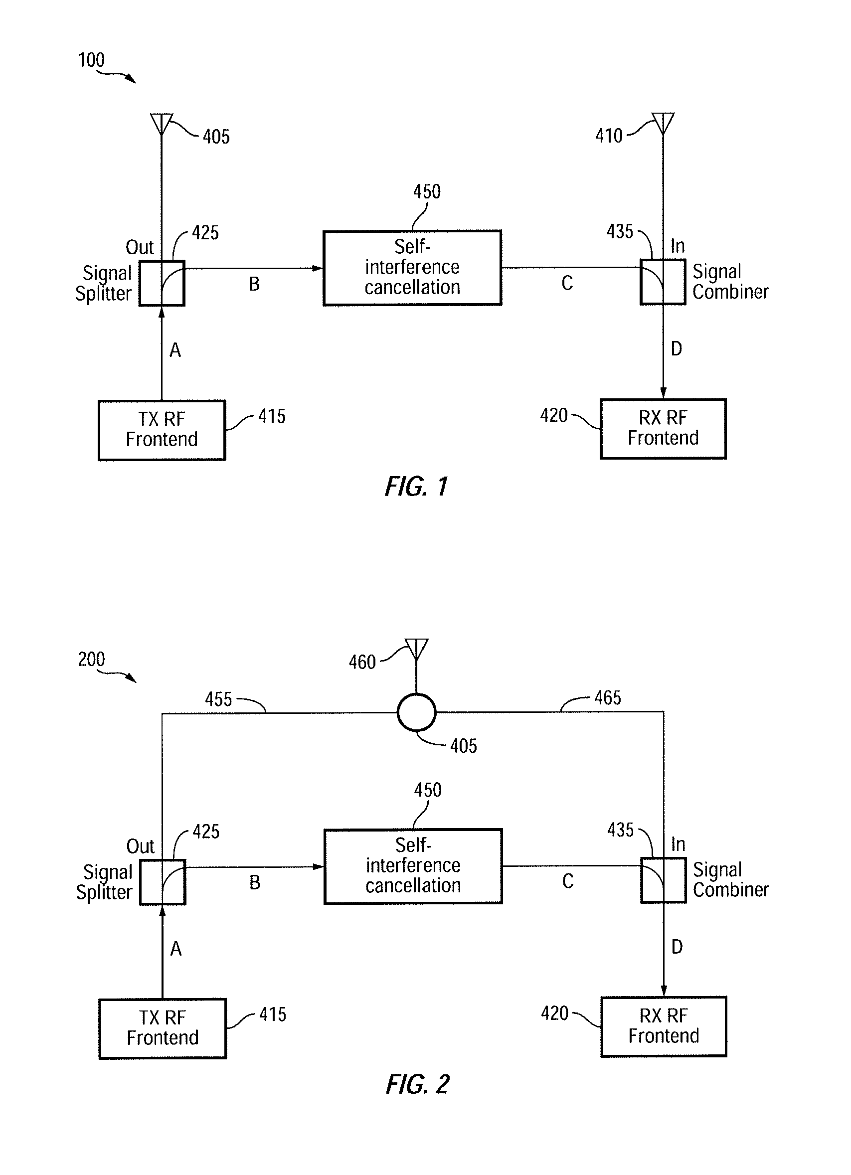
[0026]FIG. 1 is a simplified block diagram of a full-duplex wireless communication device 100, in accordance with one embodiment of the present invention. Wireless communication device 100, which may be a cellular phone, a base station, an access point or the like, is configured to transmit data / signals via transmit antenna 405 and receive data / signals via a receive antenna 410. Wireless communication device (herein alternatively referred to as device) 100 is also shown, as including, in part, a transmit front-end 415, a signal splitter 425, a receive front end 420, a signal combiner 435, and a self-interference cancellation circuit 450. Device 100 may be compatible and operate in conformity with one or more communication standards such as WiFi™, Bluetooth®, GSM EDGE Radio Access Network (“GERAN”), Universal Terrestrial Radio Access Network (“UTRAN”), Evolved Universal Terrestrial Radio Access Network (“E-UTRAN”), Long-Term Evolution (LTE), and the like.

[0027]Transmit front-end 415 ...


PUM


Abstract

A circuit that cancels a self-interference signal includes, in part, a pair of signal paths that are substantially in phase, each of which paths includes a passive coupler, a delay element and a variable attenuator. The circuit further includes, in part, a first group of P signal paths each of which is substantially in phase with the pair of paths, and a second group of M signal paths each of which is substantially out-of-phase relative to the pair of signal paths. Each of the P and M signal paths includes a delay element and a variable attenuator. Furthermore, (P−1) signal paths of the first group of P signal paths, and (M−1) signal paths of the second group of M signal paths include a passive coupler. Optionally, each of the M signal paths is optionally 180° out-of-phase relative to the pair of signal paths.

Description

CROSS-REFERENCES TO RELATED APPLICATIONS[0001]The present application claims benefit under 35 §U.S.C. 119(e) of U.S. Provisional Patent Application No. 61 / 736,726, filed Dec. 13, 2012, entitled “FEED FORWARD SIGNAL CANCELLATION”, and U.S. Provisional Patent Application No. 61 / 876,663, filed Sep. 11, 2013, entitled “CANCELLATION CIRCUIT WITH VARIABLE DELAY AND AMPLIFIER” the contents of which are incorporated herein by reference in their entirety.FIELD OF THE INVENTION[0002]The present invention relates to wireless communication, and more particularly to a full duplex wireless communication system.BACKGROUND OF THE INVENTION[0003]A wireless system often operates in a half-duplex mode to either transmit or receive data at any given time. A device operating in a full-duplex mode may simultaneously transmit and receive data. However, the simultaneous transmission and reception of data are carried out over different frequencies. For example, a full-duplex cell phone uses a first frequenc...

Claims


Application Information

Patent Timeline
IPC IPC(8): H04L5/14
CPCH04L5/1461H04L5/143H04B1/525
Inventor CHOI, JUNG-ILHONG, STEVENJAIN, MAYANKKATTI, SACHINLEVIS, PHILIPMEHLMAN, JEFF
Owner KUMU NETWORKS
Learn More