
Pyrotechnic Target and Method of Manufacture

a pyrotechnic and target technology, applied in the field of impact initiated pyrotechnic targets, can solve the problems of difficult to detect whether the clay disc has been shot, difficult to produce a pyrotechnic which can be satisfactorily ignited by the impact of a relatively low energy projectile such as a pell

Inactive Publication Date: 2014-06-19
GREEN BENJAMIN JOHN
View PDF7 Cites 9 Cited by
  • Summary
  • Abstract
  • Description
  • Claims
  • Application Information

AI Technical Summary

Benefits of technology

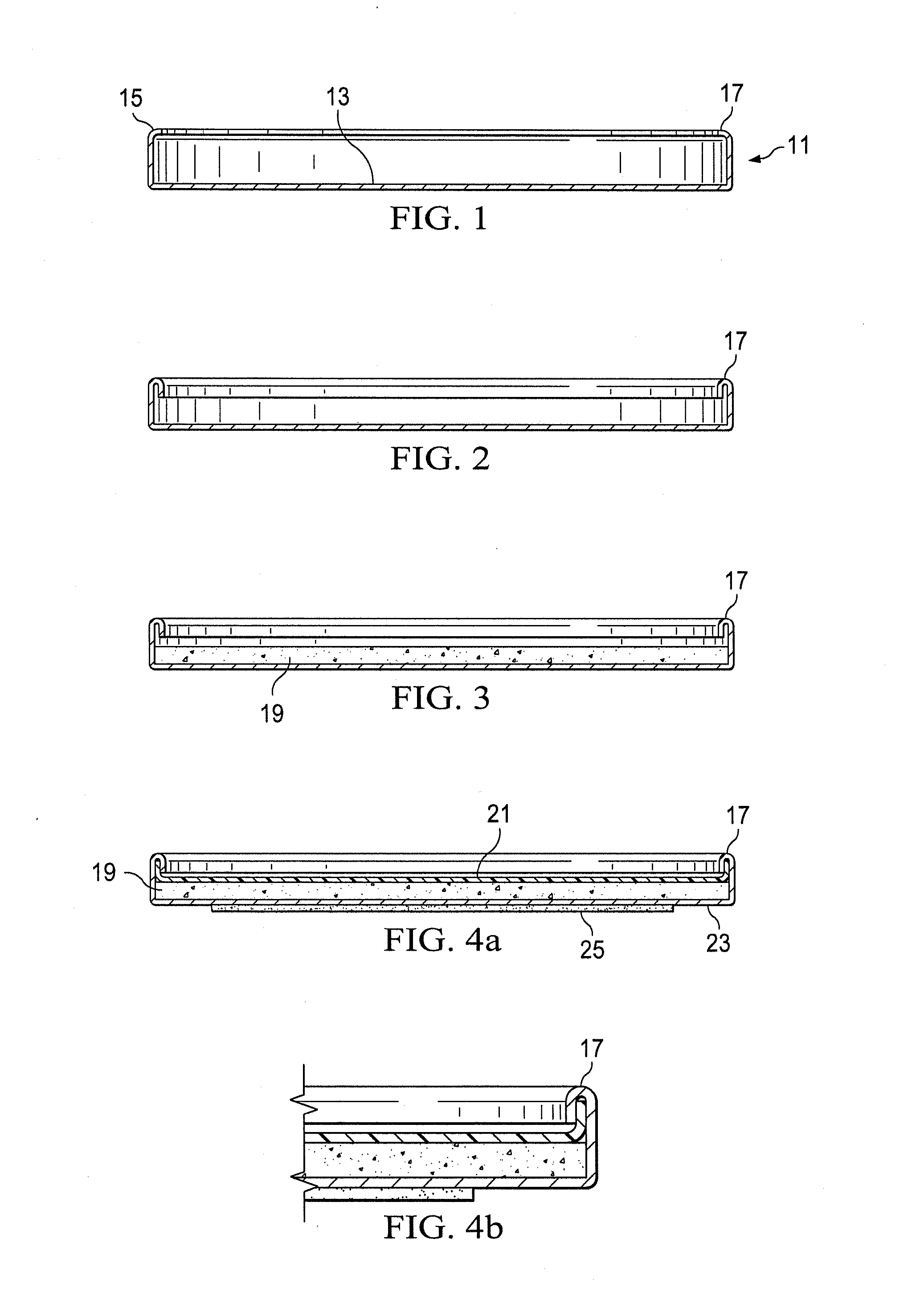
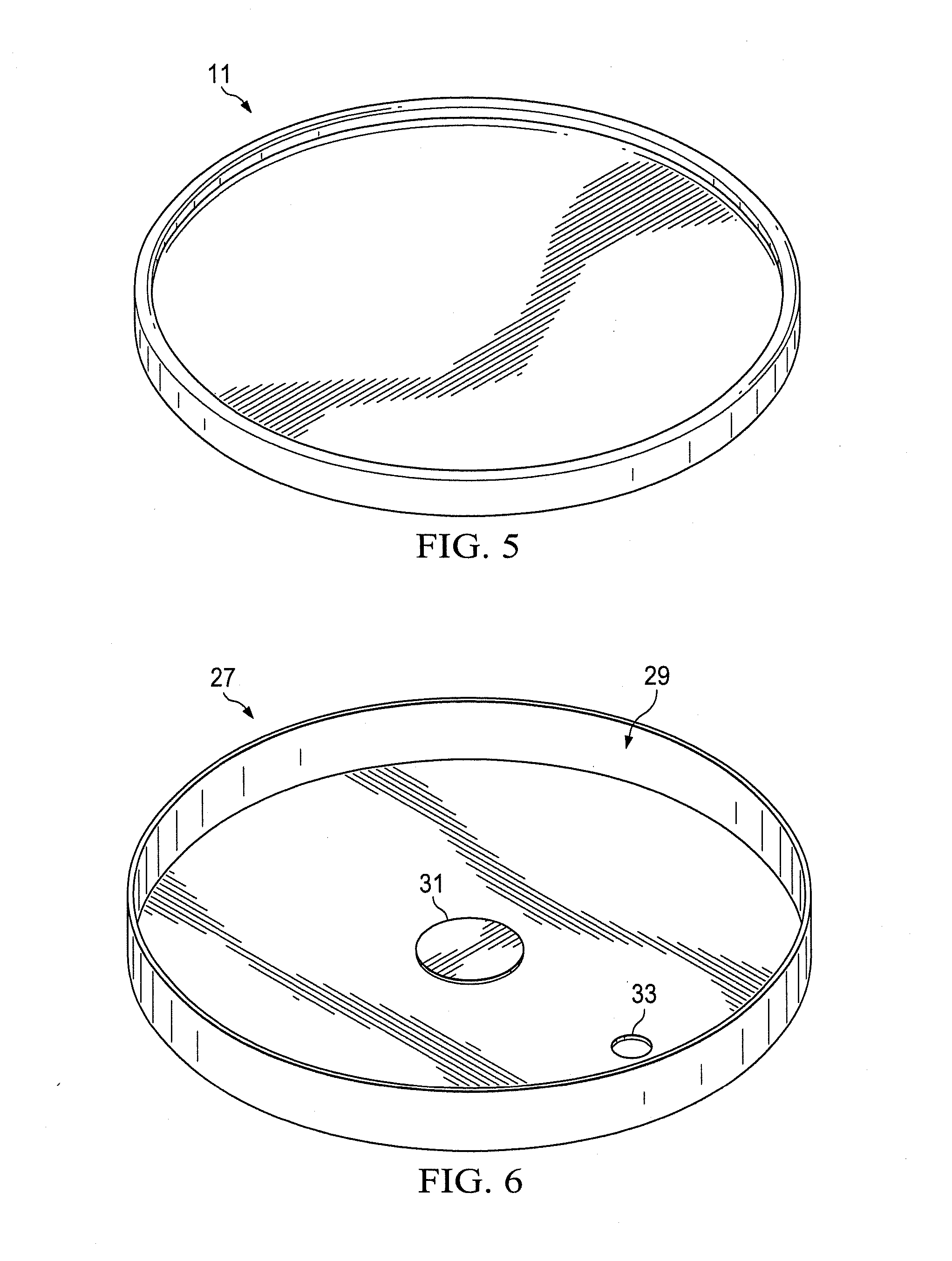
The present invention provides an impact initiated pyrotechnic target which can be initiated by the impact of an inert projectile. The target is made of a thin metal disc with a flat exposed surface and a circumscribing cylindrical lip. The exposed surface of the disc inside the lip has applied thereto a pyrotechnic composition coating layer which can be initiated by the impact of an inert projectile. A circular protective lid is snapped into place over the exposed disc surface and the pyrotechnic composition to form a completed shell casing. The pyrotechnic composition is made of pyrotechnic agents in a binder composition which is initially flowed by gravity over the exposed disc surface and then dried. The cardboard lid which is used to cover the pyrotechnic layer can be laminated with a suitable plastic so that it is water repellant. The thin metal disc used in making the completed shell casings can also be provided with an adhesive patch to allow it to be temporarily stuck to a target background surface or held within an accompanying disc receiving holder. The disc receiving holder is designed to allow for easy re-use and retains its shape even after impact. The technical effect of this invention is to provide an improved method for making an impact initiated pyrotechnic target.

Problems solved by technology

One disadvantage of the prior art targets was the fact that it could sometimes be difficult to detect whether the target had, in fact, been hit.
However, it is sometimes difficult to discern whether the clay disc has been shot as the shattering is not particularly dramatic.
However, despite advances of this kind that have been made in the field of pyrotechnic targets, it has proven difficult to produce a pyrotechnic which can be satisfactorily ignited by the impact of a relatively low energy projectile such as a pellet or slug discharged by a pneumatic weapon such as an air rifle.

Method used


Image

  • Pyrotechnic Target and Method of Manufacture
  • Pyrotechnic Target and Method of Manufacture
  • Pyrotechnic Target and Method of Manufacture

Examples


Embodiment Construction

[0022]The embodiments herein and the various features and advantageous details thereof are explained more fully with reference to the non-limiting embodiments that are illustrated in the accompanying drawings and detailed in the following description. Descriptions of well-known components and processes and manufacturing techniques are omitted so as to not unnecessarily obscure the embodiments herein. The examples used herein are intended merely to facilitate an understanding of ways in which the invention herein may be practiced and to further enable those of skill in the art to practice the embodiments herein. Accordingly, the examples should not be construed as limiting the scope of the claimed invention.

[0023]The method of manufacturing the impact initiated pyrotechnic target of the invention will now be described in greater detail. The manufacturing process begins with the empty shell casing 11 shown in FIG. 1 of the drawings. The shell casing 11 is a thin metal disc typically f...


PUM

PropertyMeasurementUnit
diameteraaaaaaaaaa
vertical heightaaaaaaaaaa

Abstract

An impact initiated pyrotechnic target is shown in the form of a thin metal disc. The disc is manufactured using a shell casing in the form of a metal disk having a flat, round exposed disc surface and a circumscribing cylindrical lip. The lip extends upwardly past the exposed disc surface and is turned in on a radius. The exposed surface of the disk inside the periphery of the cylindrical lip is coated with a pyrotechnic composition coating layer which can be initiated by the impact of an inert projectile. A cardboard lid is snapped into place over the exposed disc surface and is held in place by the turned-in periphery of the cylindrical lip of the disc.

Description

CROSS REFERENCE TO RELATED APPLICATION[0001]The present application claims priority from the earlier filed provisional application, Ser. No. 61 / 736,673, filed Dec. 13, 2012, entitled “Pyrotechnic Target and Method of Manufacture.”BACKGROUND OF THE INVENTION[0002]1. Field of the Invention[0003]The present invention relates to impact initiated pyrotechnic targets and to a method for manufacturing the same.[0004]2. Description of the Prior Art[0005]The prior art shows many examples of practice targets for use in the various shooting arts. For example, the targets described in the prior art may be used in conjunction with firearms such as shotguns, rifles and pistols, and air propelled arms such as air rifles and air pistols. They may also be used with a bow and arrow target. The target may be of the type which is intended to be held in a fixed position, and which may have indicia located thereon such as a number of concentric rings defining a “bullseye”. The target might also assume va...

Claims


Application Information

Patent Timeline
Patent Type & Authority Applications(United States)
IPC IPC(8): F41J5/14
CPCF41J5/14F41J5/24
Inventor GREEN, BENJAMIN, JOHN
Owner GREEN BENJAMIN JOHN
Learn More