
Self-powered energy conversion refrigeration apparatus

Inactive Publication Date: 2014-06-26
LINDE AG
View PDF5 Cites 3 Cited by
  • Summary
  • Abstract
  • Description
  • Claims
  • Application Information

AI Technical Summary

Benefits of technology

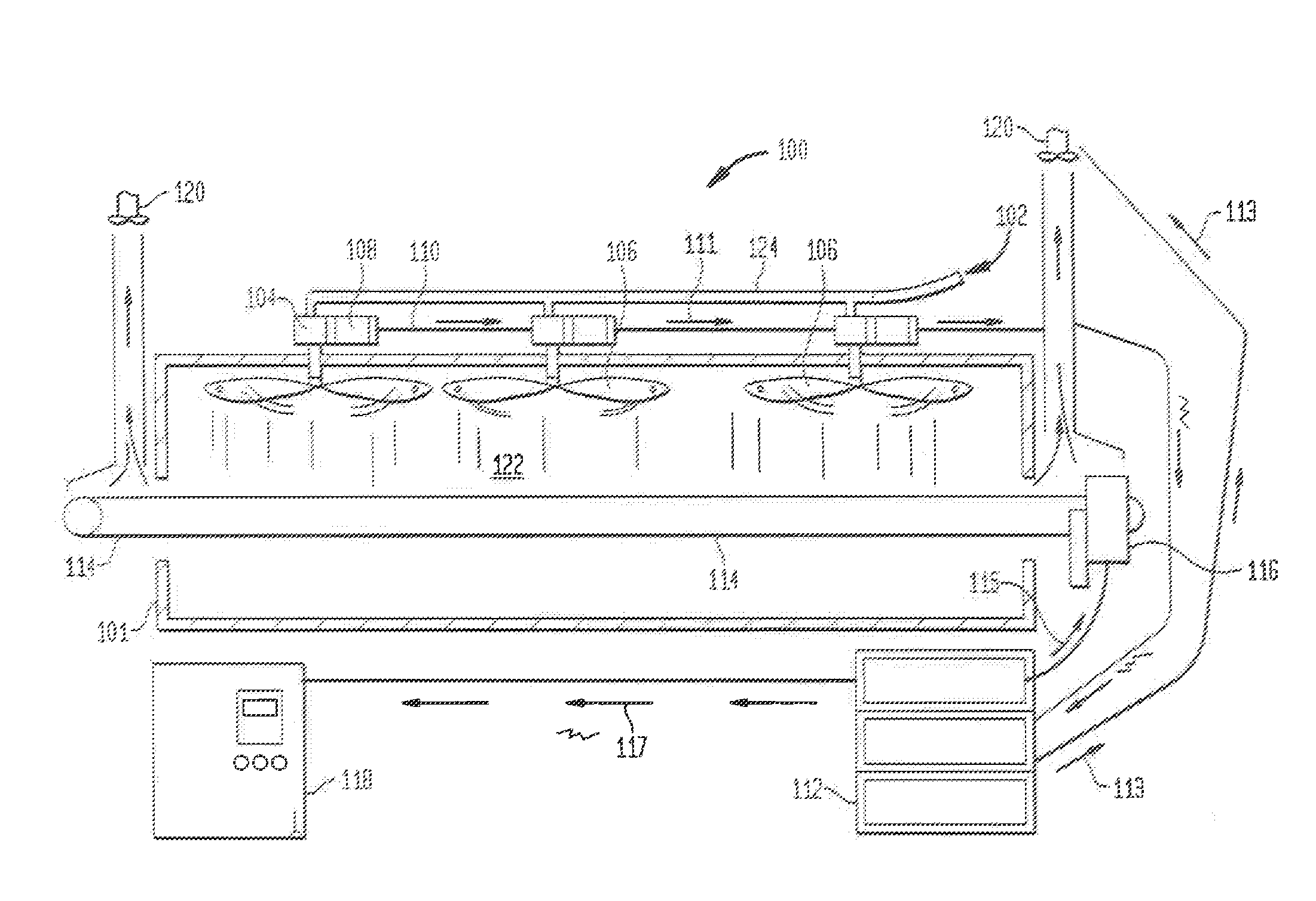
[0006]There is therefore provided an apparatus for transfer of such energy through a fan, turbine or any other rotating device which can be powered by a high pressure, high energy state, cryogenic fluid, such as CO2 or N2. Work can be accomplished with the CO2 before it is passed through the nozzles so that the energy state (enthalpy) of the CO2 liquid will be reduced. This results in the liquid effectively being subcooled before it passes across the nozzle or nozzles and

Problems solved by technology

Motors consume electrical energy and can add heat to the refrigeration apparatus if they are mounted to or within the refrigeration chamber.
Further, internal inject

Method used


Image

  • Self-powered energy conversion refrigeration apparatus
  • Self-powered energy conversion refrigeration apparatus
  • Self-powered energy conversion refrigeration apparatus

Examples


Example

Example

[0045]As mentioned above, a single fan 10 has been shown to generate in excess of 1.5 horsepower (HP). The 1.5 HP is equivalent to 3818 BTU / hr. With a flow rate of 166 lbs. of CO2 per hour being passed through the apparatus during the test, CO2 liquid at this flow rate will normally result in a 166 lbs. / hr—121 BTU / lbs=20,086 BTU / hr. The amount of energy removed in the process to power the fan is 3818 BTU / hr (1.5 horsepower (HP)=3818 btu / hr). This energy is removed from the cryogenic fluid (CO2), thereby now producing 23,904 BTU / hr of refrigeration versus the 20,086 BTU / hr without the fan for a total increase of 19 percent in refrigeration, with the added benefit of no electricity required to power the fan.

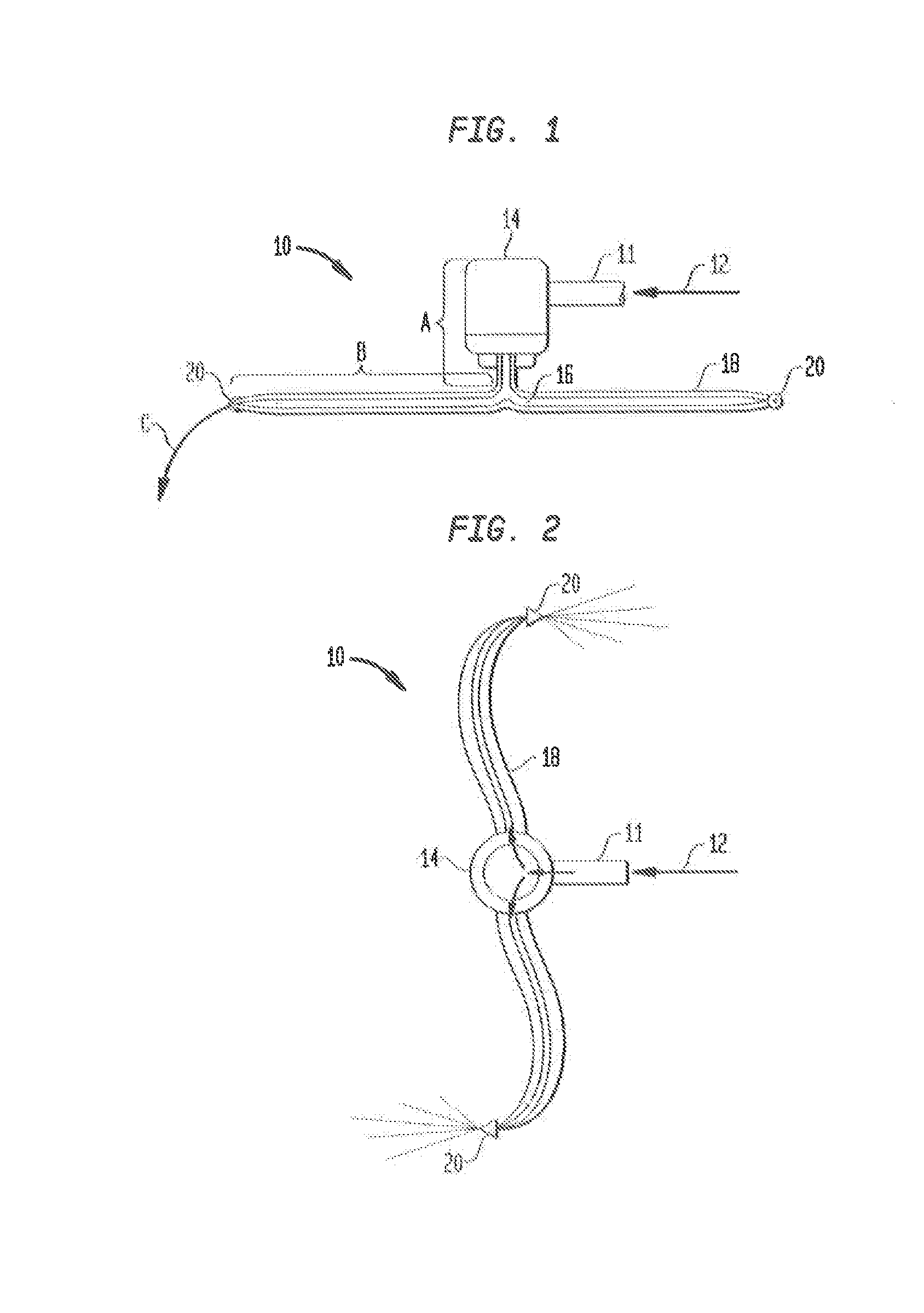
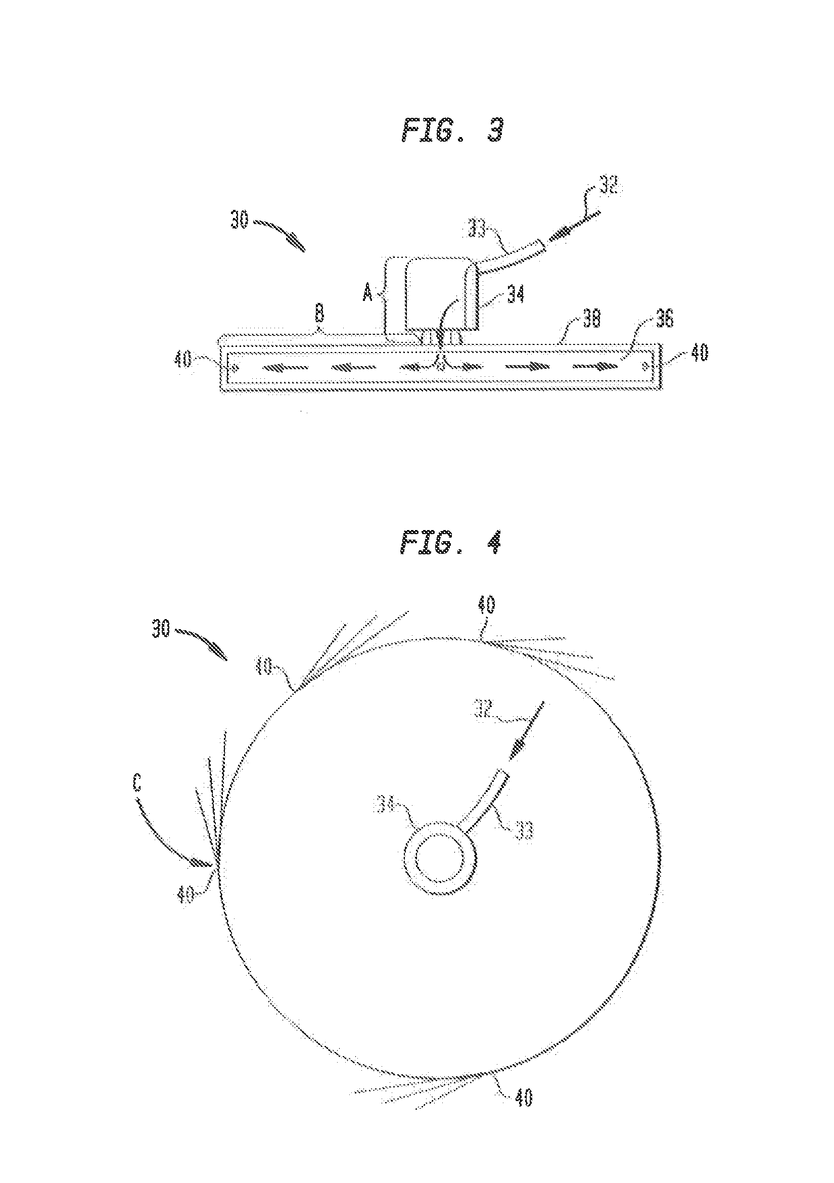
[0046]For all the inventive embodiments of FIGS. 1-9, the transition of the liquid CO2 from region B to region C causes the CO2 snow to be exhausted from the region C at its lowest pressure and energy state.

[0047]in effect, the present inventive embodiments provide an energy...


PUM


Abstract

An energy conversion apparatus for a freezer includes a housing having a first region therein for receiving liquid CO2 for providing potential energy; a movable member rotatably mounted to the housing and having a second region in fluid communication with the first region and constructed to receive the liquid CO, for providing kinetic energy from which mechanical work is provided to rotate the movable member; and a discharge member connected to the movable member and having a third region in fluid communication with the second region, the third region continuing the mechanical work when exhausting the liquid CO2 such that the liquid CO2 is changed to a CO2 snow.

Description

BACKGROUND OF THE INVENTION[0001]The present embodiments relate to apparatus for transferring potential energy of a high pressure, high energy cryogenic fluid into mechanical energy for increasing the amount of refrigeration by decreasing the enthalpy of the fluid for use with, for example cryogenic food freezers.[0002]Powering a fan in a refrigeration apparatus which utilizes a refrigerant fluid discharged directly into the refrigeration chamber requires use of electricity to operate an electric motor for the fan, the motor being mounted. either internally or externally to the refrigeration chamber. Motors consume electrical energy and can add heat to the refrigeration apparatus if they are mounted to or within the refrigeration chamber. Further, internal injection headers required to distribute the refrigerant fluid into the refrigeration chamber consume electricity and produce additional unwanted heat within the chamber.[0003]Such refrigeration apparatus may also have ancillary s...

Claims


Application Information

Patent Timeline
IPC IPC(8): F17C9/04
CPCF25D3/11F25D3/127F17C9/04F25D2317/0681F25D17/06
Inventor NEWMAN, MICHAEL D.
Owner LINDE AG
Learn More