Air conditioning system

Inactive Publication Date: 2010-06-08
DAIKIN IND LTD
View PDF15 Cites 2 Cited by
  • Summary
  • Abstract
  • Description
  • Claims
  • Application Information

AI Technical Summary

Benefits of technology

[0036]In the present invention, the refrigerant circuit (40) is provided with one or more adsorption heat exchangers (56, 57) as utilization side heat exchangers and the air conditioning system controls the absolute humidity of the air by passing the air through the adsorption heat exchanger (56, 57). Specifically, the air conditioning system dehumidifies the air not by condensing moisture in the air as in the known system but by adsorbing moisture in the air on the adsorbent. This eliminates the need to set the refrigerant evaporation temperature in the refrigeration cycle below the air dew point unlike the known system and enables the air to be dehumidified even if the refrigerant evaporation temperature is set at the air dew point or higher. Therefore, according to the present invention, the refrigerant evaporation temperature in the refrigeration cycle can be set higher than in the known system even when the air is dehumidified, which reduces the difference between high and low pressures in the refrigeration cycle. As a result, power required for refrigerant compression can be reduced, thereby improving the COP of the refrigeration cycle.
[0037]Particularly, in the first solution, the whole of the refrigerant circuit (40) is disposed either in or outside the building. This eliminates the need for a

Problems solved by technology

This provides a large difference between high and low pressures in the refrigeration cycle and raises the input to the compressor, which leads to a problem that only a small COP (

Method used


Image

  • Air conditioning system
  • Air conditioning system
  • Air conditioning system

Examples


Example

Embodiment 1 of the Invention

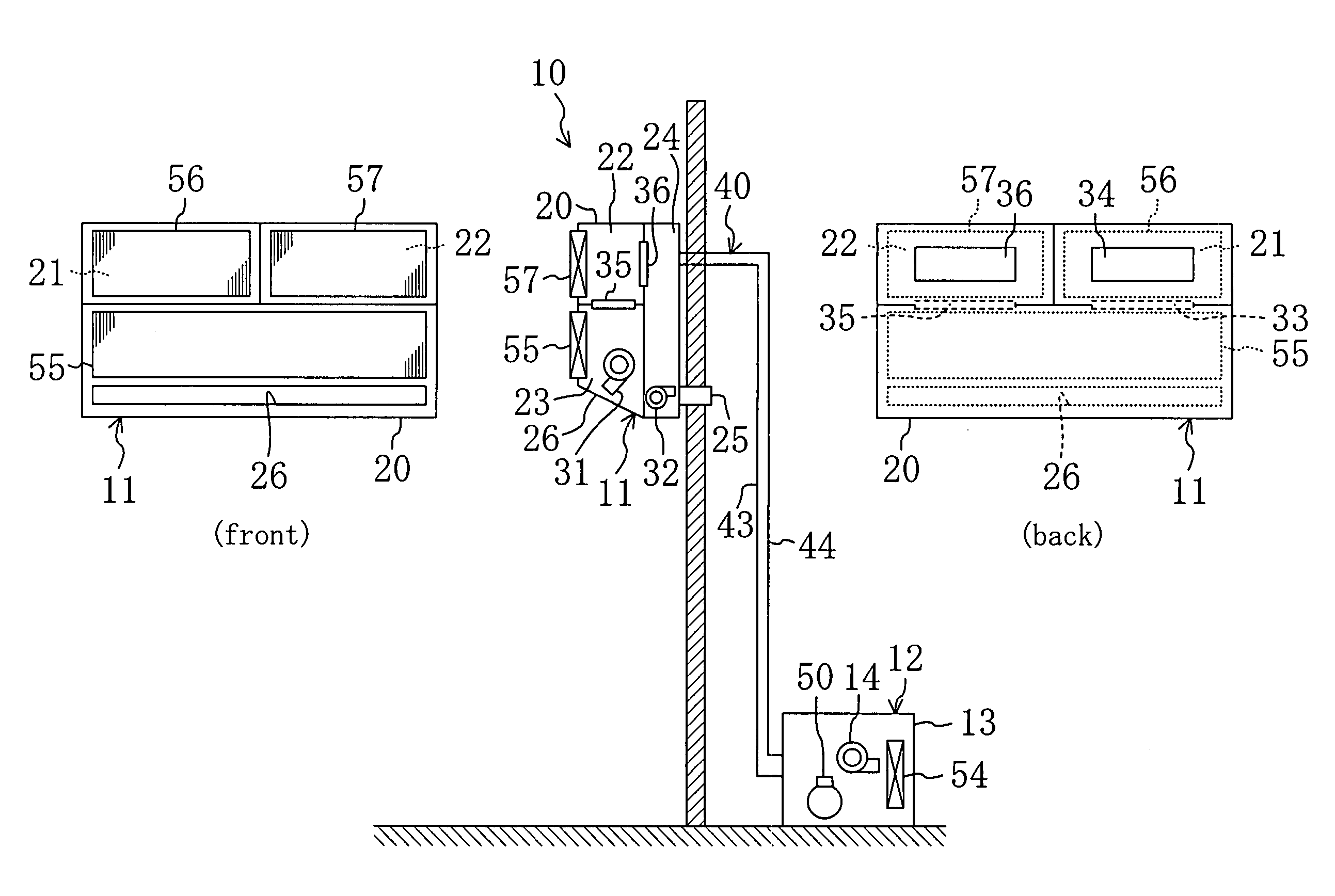
[0070]Embodiment 1 of the present invention is described. An air conditioning system (10) of the present embodiment runs a vapor compression refrigeration cycle by circulating refrigerant through a refrigerant circuit (40) to cope with both of indoor sensible heat load and latent heat load.

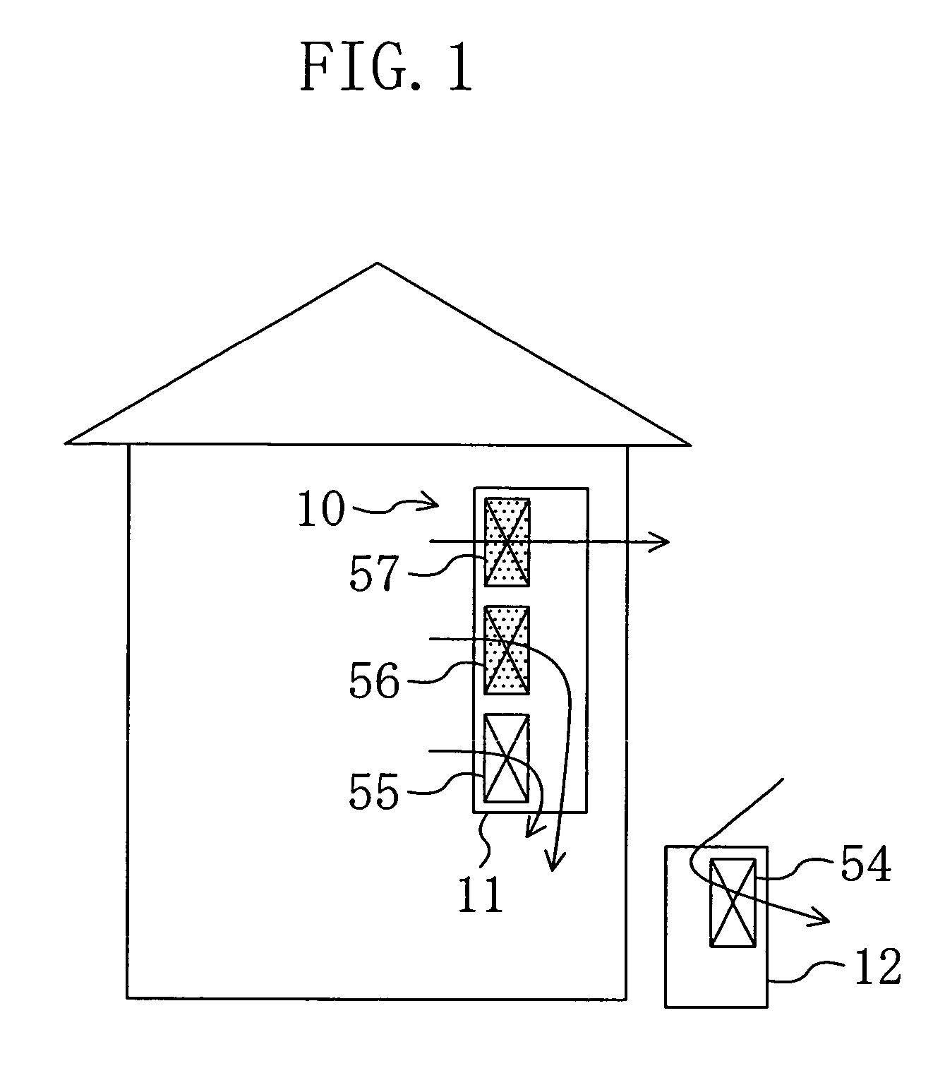
[0071]As shown in FIG. 1, the air conditioning system (10) is configured as a so-called separate type and includes an indoor unit (11) and an outdoor unit (12). The indoor unit (11) includes an indoor heat exchanger (55), a first adsorption heat exchanger (56) and a second adsorption heat exchanger (57) and is disposed in the building. The indoor unit (11) is configured as a so-called wall-mounted type, namely, is mounted on a wall surface of a room. On the other hand, the outdoor unit (12) includes an outdoor heat exchanger (54) and is disposed outside the building.

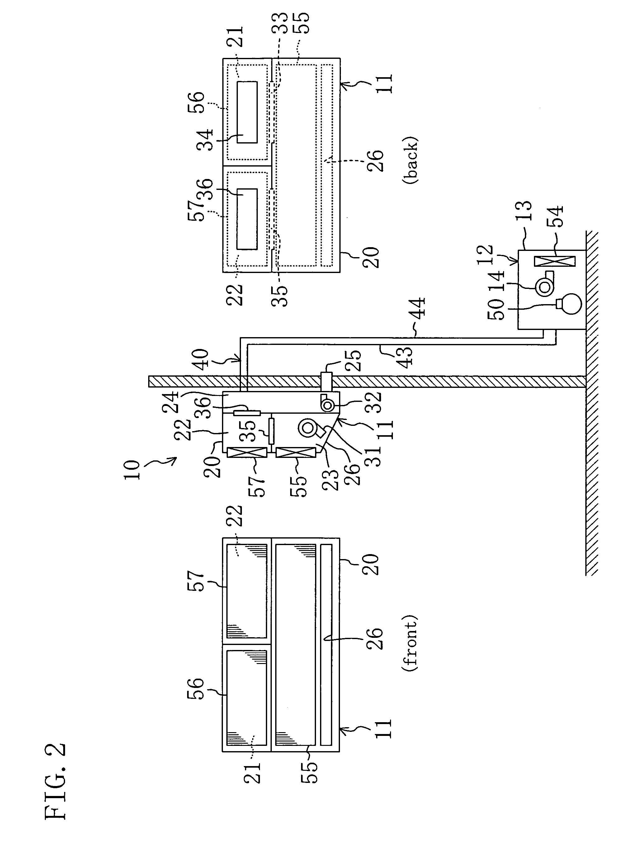
[0072]As shown in FIG. 2, the indoor unit (11) and the outdoor unit (12) are connected to each other via...

Example

[0117]Embodiment 2 of the present invention is described. Though the air conditioning system (10) of Embodiment 1 is configured as a separate type which includes an indoor unit (11) and an outdoor unit (12), the air conditioning system (10) of the present embodiment is configured as an integral type in which all components are contained in a single main unit casing (60). A description is given here to the air conditioning system (10) of the present embodiment only in different points from that of Embodiment 1.

[0118]As shown in FIG. 13, the air conditioning system (10) of the present embodiment is disposed in the attic of a building such as a house and connected to the room space and the outdoor space through ducts. The air conditioning system (10) contains a whole refrigerant circuit (40) in the main unit casing (60) disposed in the attic. Therefore, the refrigerant circuit (40) of the present embodiment is wholly disposed in the building.

[0119]In the refrigerant circuit (40), an ex...

Example

[0156]Embodiment 3 of the present invention is described. An air conditioning system (10) of the present embodiment varies from Embodiment 1 in the arrangement of the first adsorption heat exchanger (56) and the second adsorption heat exchanger (57). A description is given here to the present embodiment only in different points from Embodiment 1.

[0157]As shown in FIGS. 19 and 20, in the air conditioning system (10) of the present embodiment, a first adsorption heat exchanger (56) and a second adsorption heat exchanger (57) are contained in an outdoor unit (12). Specifically, an outdoor casing (13) for the outdoor unit (12) contains an outdoor heat exchanger (54) and an outdoor fan (14) like Embodiment 1 and additionally contains the two adsorption heat exchangers (56, 57). Further, in an indoor unit (11). of the present embodiment, an indoor casing (20) contains an indoor heat exchanger (55) and an indoor fan (31).

[0158]As shown in FIGS. 20 and 21, the outdoor heat exchanger (54) is...


PUM


Abstract

A refrigerant circuit (40) is provided with two adsorption heat exchangers (56, 57) in addition to an outdoor heat exchanger (54) and an indoor heat exchanger (55). The indoor heat exchanger (55) and the two adsorption heat exchangers (56, 57) are disposed in an indoor unit (11), while the outdoor heat exchanger (54) is disposed in an outdoor unit (12). In the adsorption heat exchanger (56, 57) serving as an evaporator, moisture in the air is adsorbed by the adsorbent. In the adsorption heat exchanger (56, 57) serving as a condenser, moisture is desorbed from the adsorbent and then applied to the air. Then, the air dehumidified or humidified by the adsorption heat exchanger (56, 57) is supplied to a room to cope with latent heat load in the room. On the other hand, in the indoor heat exchanger (55), air is cooled or heated. Then, the air cooled or heated by the indoor heat exchanger (55) is supplied to the room to cope with sensible heat load in the room.

Description

TECHNICAL FIELD[0001]This invention relates to air conditioning systems for coping with indoor sensible heat load and latent heat load.BACKGROUND ART[0002]An air conditioning system providing cooling and dehumidification of a room is known in the art as disclosed in WO03 / 029728 pamphlet. The air conditioning system includes a refrigerant circuit provided with a heat-source side outdoor heat exchanger and a utilization side indoor heat exchanger and runs a refrigeration cycle by circulating refrigerant through the refrigerant circuit. Further, the air conditioning system dehumidifies the room by setting the refrigerant evaporation temperature in the indoor heat exchanger below the dew point of the room air and condensing moisture in the room air.[0003]A dehumidifier is also known which includes heat exchangers each provided with an adsorbent on the surface thereof, as disclosed in Japanese Unexamined Patent Publication No. H07-265649. The dehumidifier includes two heat exchangers and...

Claims


Application Information

Patent Timeline
IPC IPC(8): F28D5/00B01D53/26F24F1/00F24F3/14F24F7/08F25B5/04F25B6/04F25B13/00F25B29/00
CPCB01D53/261F24F3/1411F24F3/1429F25B13/00F25B2313/02343B01D53/26F24F3/12F24F3/14
Inventor MATSUI, NOBUKIIKEGAMI, SHUJIYABU, TOMOHIRO
Owner DAIKIN IND LTD
Why Eureka
Try Eureka