
Ammonia plant

a technology for ammonia plants and ammonia, applied in the direction of machine operation, light and heating equipment, chemical production, etc., can solve the problems of affecting the operation of the plant, the retrofitting of the existing plant is problematic, and the demand for excess air is still relatively high

Active Publication Date: 2015-09-08
FLUOR TECH CORP
View PDF12 Cites 0 Cited by
  • Summary
  • Abstract
  • Description
  • Claims
  • Application Information

AI Technical Summary

Benefits of technology

The patent is about a new way to increase the efficiency of an ammonia synthesis plant by increasing the pressure difference between the bottom product of a cryogenic separator and the processed syngas overhead product. This is achieved by expanding the bottom product and compressing or pumping it to increase the pressure difference, which leads to increased refrigeration cold. The technical effect of this new method is increased efficiency of the ammonia synthesis plant.

Problems solved by technology

While Grotz's configuration is relatively effective in some ammonia production plants, retrofitting of existing plants is problematic since the expansion step requires considerable increase in front-end pressure in a ammonia synthesis plant and thereby typically necessitates retrofits / rebuilds to accommodate for the increased pressure.
Although Bhakta's configuration overcomes in many cases the need for retrofitting existing plants, Bhakta's configuration is typically limited to relatively narrow process parameters in order to provide satisfactory improvements in synthesis capacity.
While such configurations provide numerous advantages over previously known ammonia plants, demands for excess air are still relatively high.
Therefore, despite numerous known configurations and processes for improvements of ammonia synthesis, all or almost all of them suffer from one or more disadvantages.

Method used


Image

  • Ammonia plant
  • Ammonia plant
  • Ammonia plant

Examples


Embodiment Construction

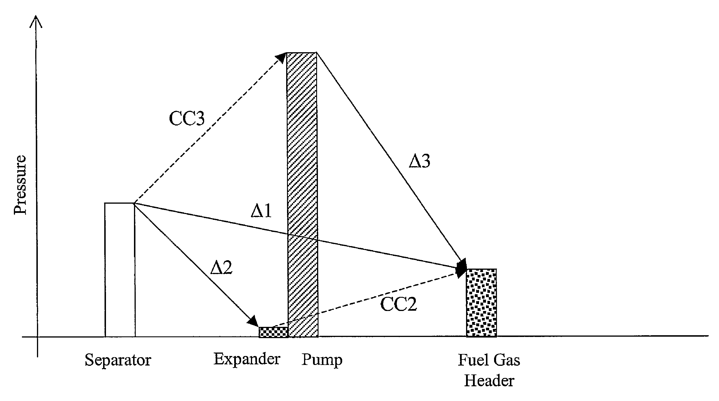
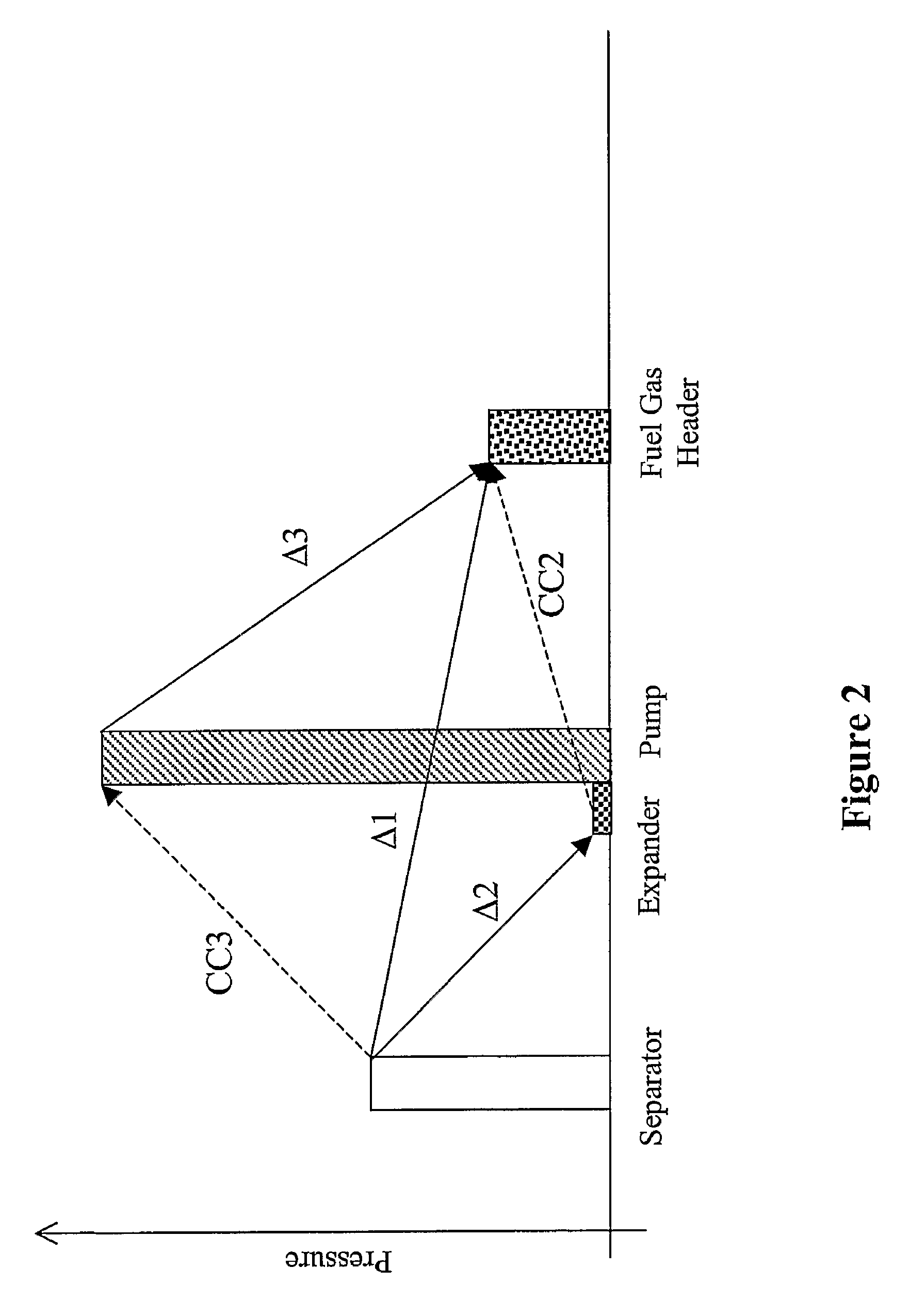
[0018]The inventors have discovered that the amount of excess air in ammonia plants can be substantially reduced by increasing refrigeration in the coldbox rectifier. In most preferred configurations, the refrigeration is increased by increasing a pressure gradient in the rectifier bottom product, which is expanded to thereby generate refrigeration cold. Thus, contemplated configurations will advantageously reduce excess air rate (e.g., 37% versus 50% for the standard Braun process), which will also result in a lower hydraulic load in the front end of the plant and / or a lower CO2 removal system duty.

[0019]For example, in one aspect of the inventive subject matter, the bottom product is over-expanded (i.e., expanded to a pressure below a delivery pressure to a downstream device) and then re-compressed using energy provided by raw syngas expansion. Alternatively, bottom product may also be pumped to a desired pressure using energy provided by raw syngas expansion, and the so pressuriz...


PUM

PropertyMeasurementUnit
atmospheric pressureaaaaaaaaaa
pressureaaaaaaaaaa
pressureaaaaaaaaaa

Abstract

A synthesis plant (309A) includes a compression device (360A) that increases a pressure differential between the bottom product pressure of a cryogenic separator (340A) and the delivery pressure of the bottom product to a downstream plant component. Such increased pressure differential is employed to increase cooling in the separator (340A) to thereby significantly reduce the volume of excess air. In most preferred aspects, at least part of the energy required for the compression device is provided by expansion (320A) of the separator feed.

Description

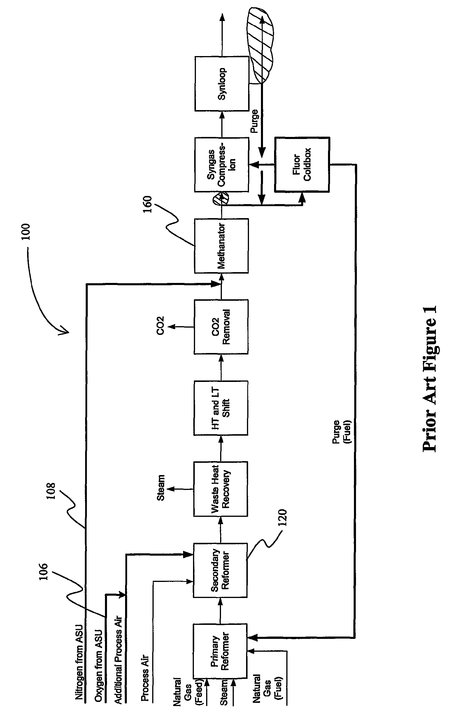
[0001]This application claims priority to our U.S. provisional patent application with the Ser. No. 60 / 592,930, which was filed Jul. 29, 2004.FIELD OF THE INVENTION[0002]The field of the invention is configurations and methods for ammonia production.BACKGROUND OF THE INVENTION[0003]In most conventional ammonia plants, natural gas is processed in primary and secondary reformers to generate hydrogen, and the reformed gas stream is then subjected to a shift conversion for additional hydrogen production after excess heat has been recovered from the reformed gas stream. In a still further step, acid gases (here: carbon dioxide) are removed and residual carbon monoxide (CO) and carbon dioxide (CO2) are converted into methane in a downstream methanator. The resulting raw synthesis gas stream is then passed into the synthesis loop for production of ammonia, wherein the nitrogen is typically provided from process air that is fed into the secondary reformer.[0004]Typically, an ammonia plant w...

Claims


Application Information

Patent Timeline
Patent Type & Authority Patents(United States)
IPC IPC(8): C01C1/04F25J3/02C01B3/02
CPCC01C1/0405C01B3/025F25J3/0219F25J3/0276F25J2200/02F25J2200/74F25J2200/80F25J2210/20F25J2230/20F25J2235/02F25J2240/02F25J3/0233F25J2235/60Y02P20/52
Inventor REDDY, SATISHBHAKTA, MUKUNDSCHERFFIUS, JEFFREY
Owner FLUOR TECH CORP
Learn More