Locating Of Pressure Taps On Face Of Orifice Plate Device

Active Publication Date: 2008-12-18
DIETERICH STANDARD
View PDF15 Cites 25 Cited by
  • Summary
  • Abstract
  • Description
  • Claims
  • Application Information

AI Technical Summary

Problems solved by technology

However, if the velocity profile is skewed, the differential pressure across the constricting plate will not be a true indication of the rate of fluid flow.
However, even when such ideally simplistic flow conditioning devices are utilized, instead of upstream flow straighteners, disturbances to the pressure measuring ports, which are typically placed on

Method used


Image

  • Locating Of Pressure Taps On Face Of Orifice Plate Device
  • Locating Of Pressure Taps On Face Of Orifice Plate Device
  • Locating Of Pressure Taps On Face Of Orifice Plate Device

Examples


Embodiment Construction

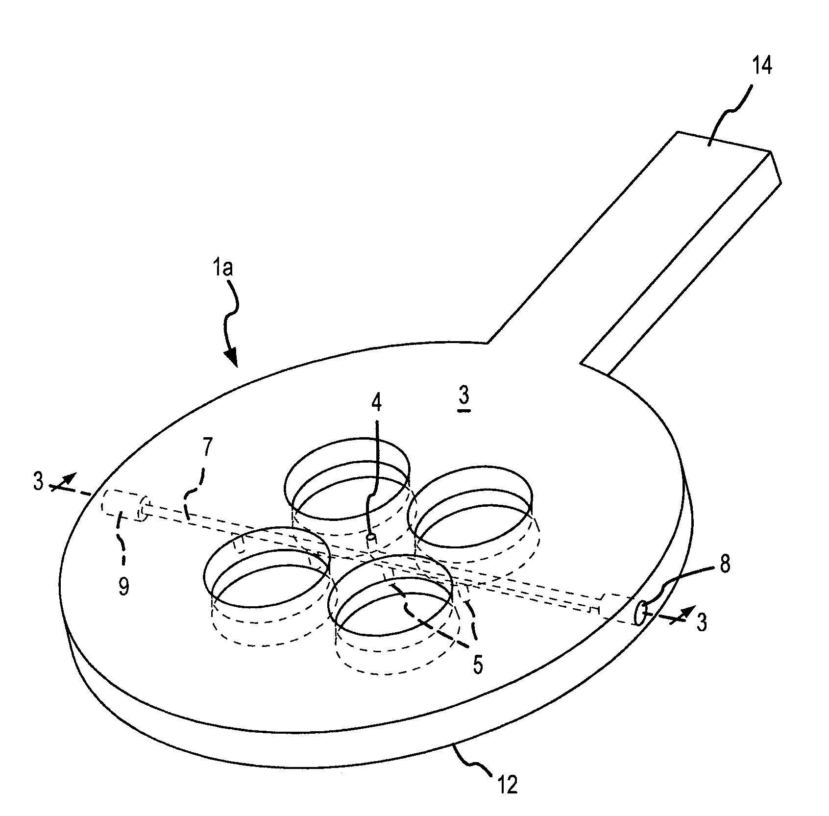
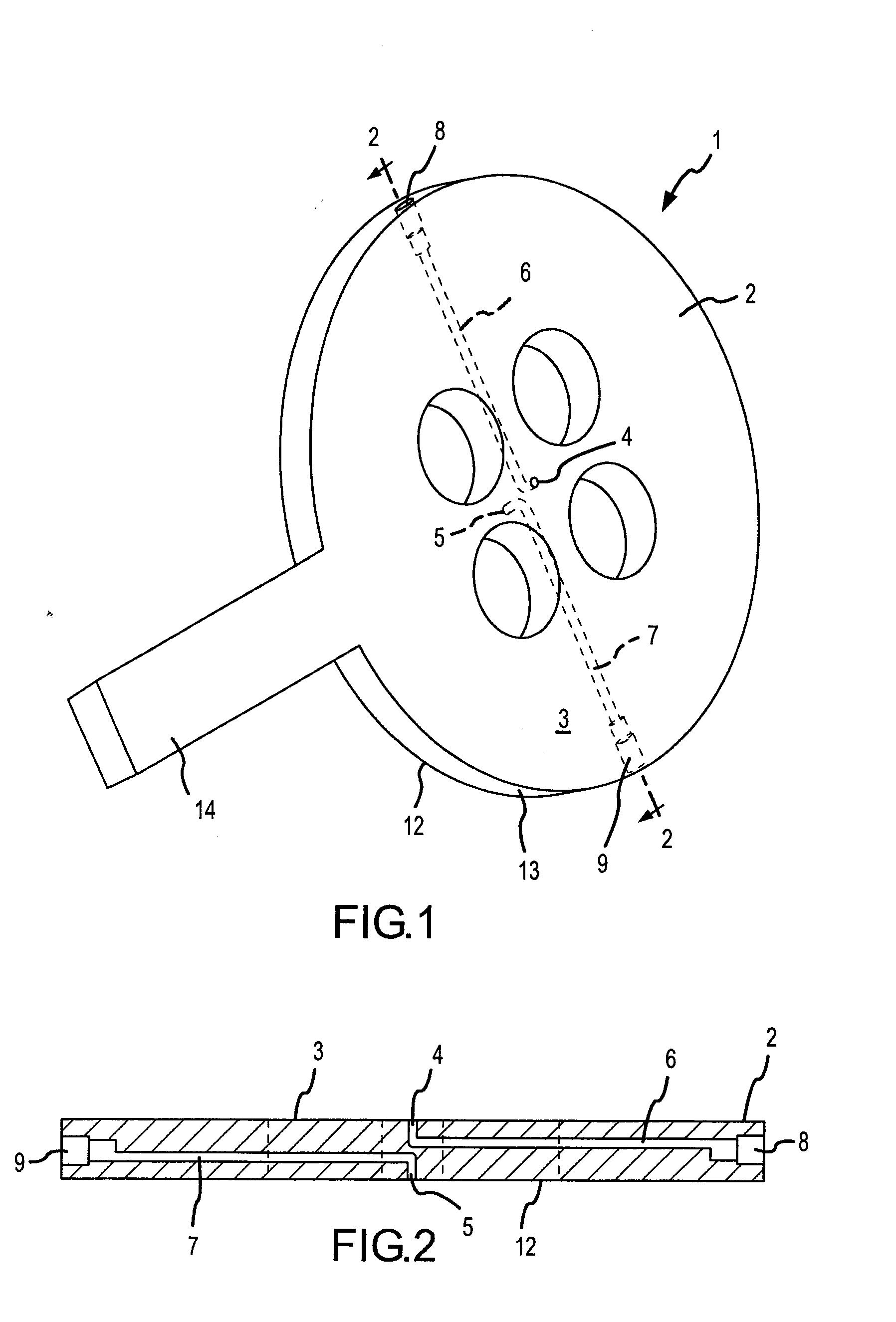
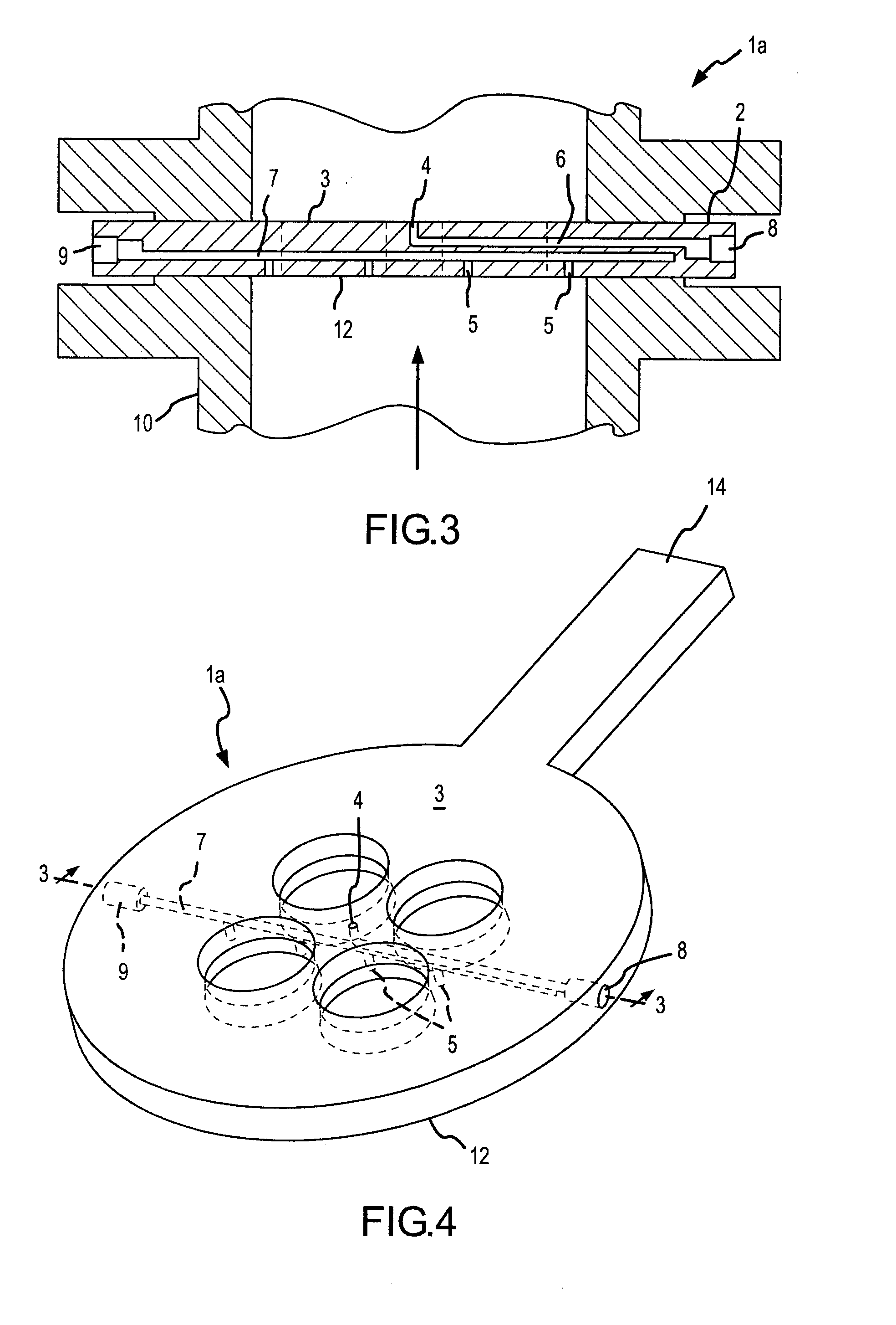
[0021]A simplified version of the present invention is shown in FIGS. 1 and 2. The averaging orifice plate flow element comprises a flat plate 1 having a circular portion 2 and a stem 14. On a diametric line across the circular portion there is disposed within the plate a first conduit or bore 6 that interconnects the opening 4 in the downstream face 3 of the circular portion 2 of the plate to a first pressure sensing port 8 disposed in the circumferential edge 13 of the circular portion 2 of the plate. A second conduit or bore 7 interconnects an opening 5 in the upstream face 12 of the plate to a second pressure sensing port 9 in the circumferential edge 13 of the circular portion 2. The pressure ports are arranged to be connected to a traditional fluid manifold (not shown) and into a pressure transducer (not shown). An electrical signal that represents the sensed differential pressure between the ports 8 and 9 is transmitted by transmitter (not shown) to a processing unit (not sho...


PUM


Abstract

A process flow device that includes a self-averaging orifice plate type of primary flow element with a high pressure tap located on or incorporated into its upstream surface, and a low pressure tap located on or incorporated into its downstream surface, for measuring, by a differential pressure process, the volumetric rate of fluid flow at a point in a fluid carrying conduit where the velocity profile of the fluid is asymmetric with respect to the longitudinal axis of the conduit. The improved pressure tap configuration consists of two fluid conduits, one carried by each of the downstream and upstream faces of the orifice plate, establishing fluid communication between openings in the downstream and upstream faces of the orifice plate and their respective terminal pressure ports. Location of the pressure taps on the faces of the orifice plate in this manner allows for increased resolution of the pressure signals by minimizing the effects of upstream pipe flow disturbances on pressure taps used in conjunction with conditioning orifice plate primary flow elements, especially those with higher beta ratios.

Description

FIELD OF THE INVENTION[0001]The present invention relates generally to a process flow device that includes a multiple aperture orifice plate type of primary flow element having at least one pressure tap located on its face in order to minimize disturbances in measuring, by a differential pressure process, the volumetric rate of fluid flow at a point in a fluid carrying conduit.BACKGROUND OF THE INVENTION[0002]Differential pressure process flow meters, long known in the art, measure the rate of flow of a liquid or gas by calculating the difference in pressure between a measurement taken at a high pressure tap upstream of a process flow device, and a low pressure tap downstream of the process flow device. When the primary flow element used is an orifice plate within a fluid carrying conduit such as a pipe, commonly used pressure tap types include: flange taps, corner taps, D & D / 2 taps, and pipe taps. Although the tap configuration and axial distances from the orifice plate differ, al...

Claims


Application Information

Patent Timeline
IPC IPC(8): G01F1/42
CPCG01F1/42
Inventor IFFT, STEPHEN ARTHURORLESKIE, CHARLES THEODORE
Owner DIETERICH STANDARD
Why Eureka
Try Eureka