Gas turbine and sealing means for a gas turbine

a gas turbine and sealing means technology, applied in the field of gas turbines, can solve problems such as the displacement of components with respect to one another, and achieve the effect of improving the sealing action

Inactive Publication Date: 2007-02-01
SIEMENS AG
View PDF8 Cites 29 Cited by
  • Summary
  • Abstract
  • Description
  • Claims
  • Application Information

AI Technical Summary

Benefits of technology

[0016] A simple overlapping of the collars arranged on the adjacent rings and extending in the direction of divergence is afforded when the front wing, as seen in the flow direction, has the radially inner collar and the rear ring has the outer collar, so that, as seen radially, the annular gap runs counter to the flow direction of the working fluid. This arrangement impedes the deeper inflow of the hot gas into the gap to be sealed off, since the hot gas loses kinetic energy during penetration as a result of the reversal in flow direction brought about by a bend at right angles. The spring element is thus acted upon by the hot gas solely by a lower radially outward-directed force than the spring prestress.
[0019] Especially advantageous is the embodiment in which, outside the inner casing, a cooling medium can flow, the pressure of said cooling medium being higher than the pressure of the working fluid inside the inner casing, and in which the spring action of the sealing means runs in the direction of the pressure drop. As a result, the spring action of the spring element is assisted by the appreciable pressure drop between the cooling medium and working fluid. The additional pressure force thus generated is dependent on the area of the spring element on which the cooling medium can act and becomes higher with a rising pressure difference. The additional pressure force leads to an improved sealing action. Even in the event that the spring prestress diminishes, a reliable bearing of the free end of the spring element against the annular bearing surface is thus ensured during operation.

Problems solved by technology

When the gas turbine is in operation, thermal expansions arise on the components acted upon by hot gas, such as the guide blades and their platforms, and may lead to a displacement of the components with respect to one another.

Method used


Image

  • Gas turbine and sealing means for a gas turbine
  • Gas turbine and sealing means for a gas turbine
  • Gas turbine and sealing means for a gas turbine

Examples


Embodiment Construction

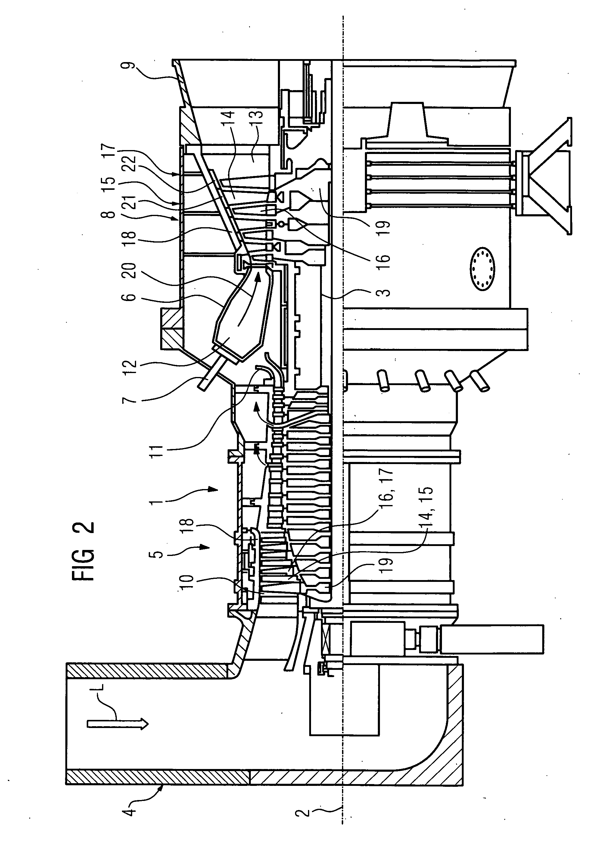
[0026]FIG. 2 shows a gas turbine 1 in a part longitudinal section. It has, inside it, a rotor 3 which is rotationally mounted about an axis of rotation 2 and which is also designated as a turbine rotor or rotor shaft. An intake casing 4, a compressor 5, a toroidal annular combustion chamber 6 with a plurality of coaxially arranged burners 7, a turbine 8 and an exhaust gas casing 9 succeed one another along the rotor 3.

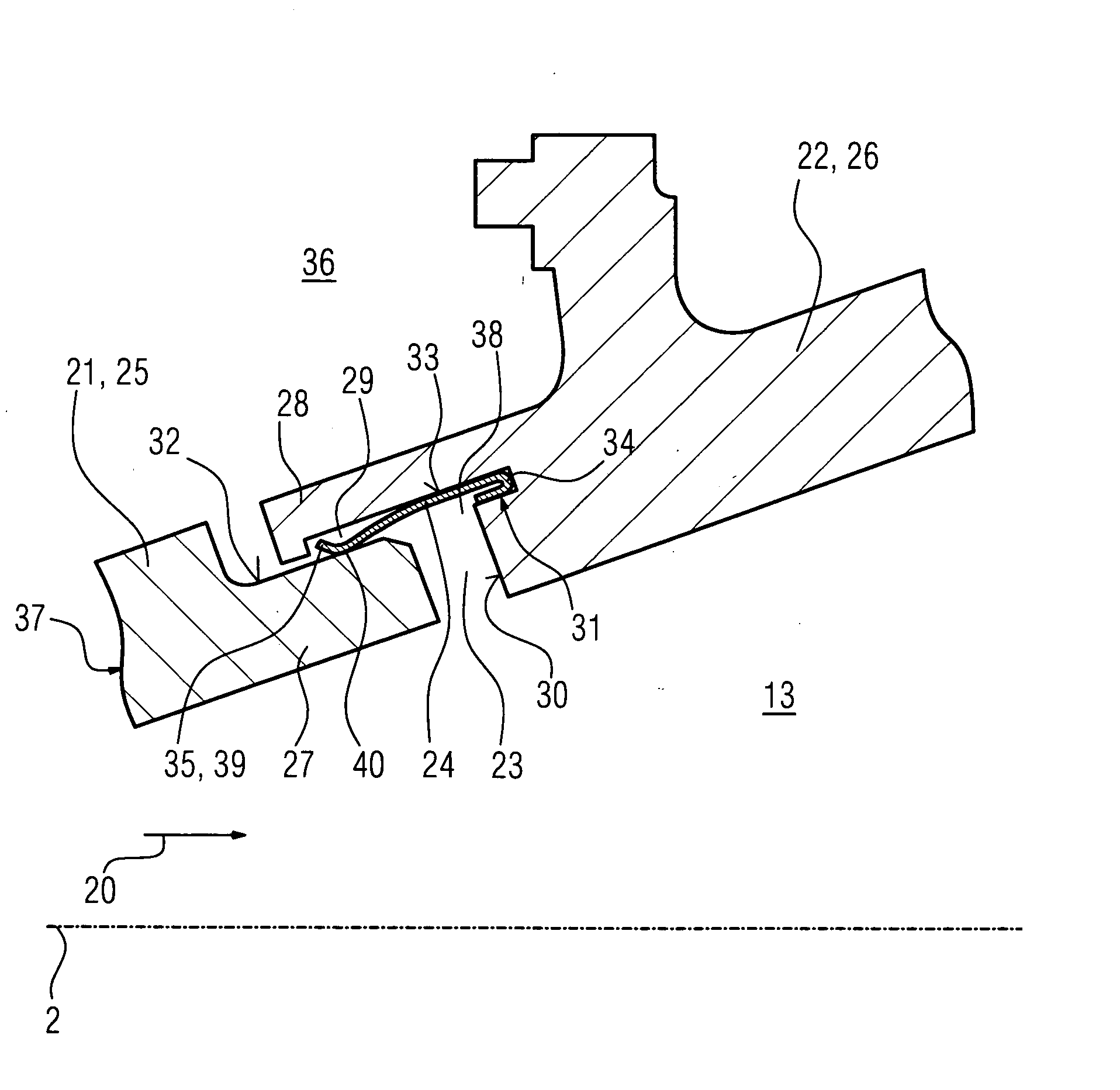
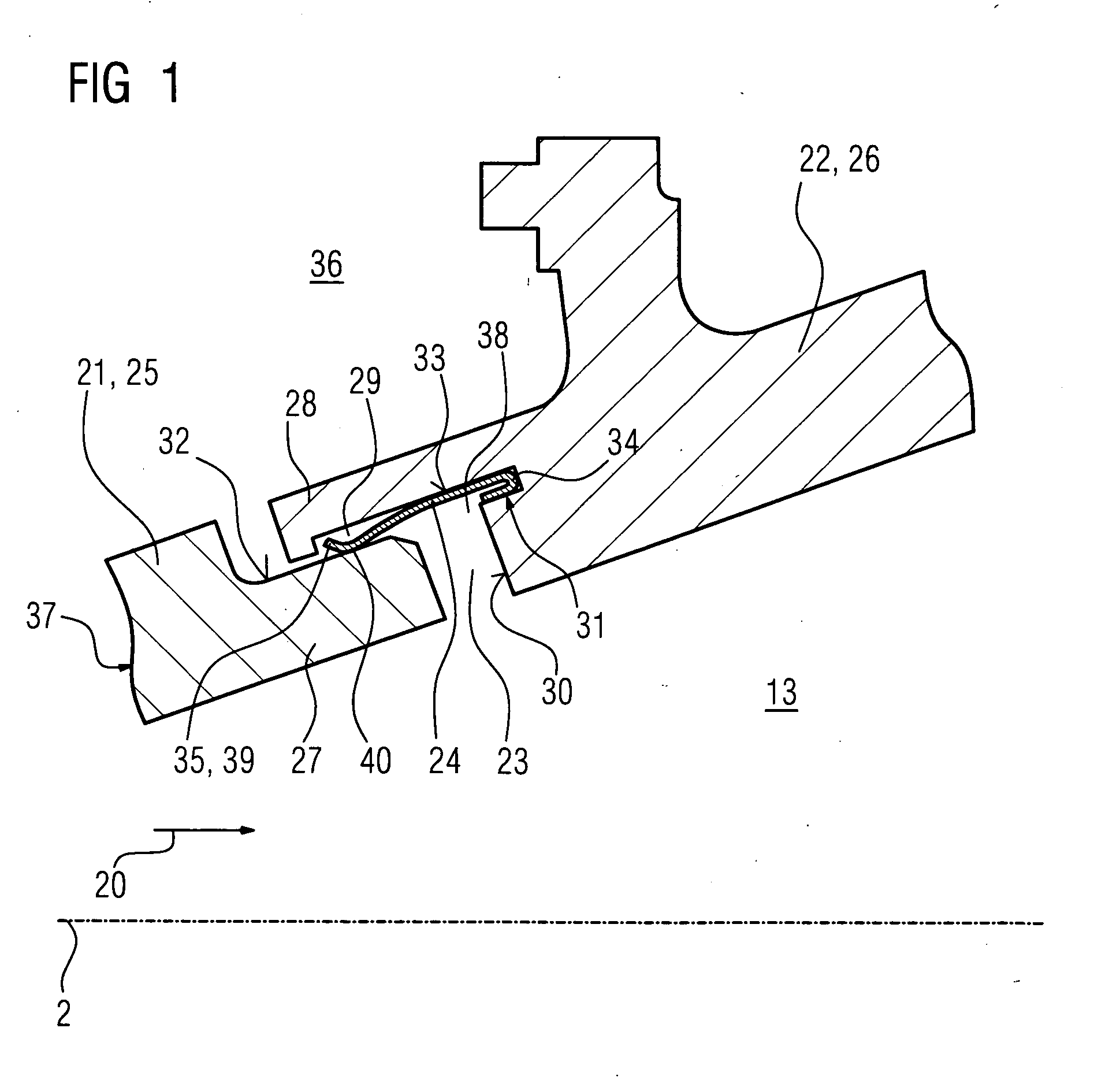
[0027] In the compressor 5, an annular compressor duct 10 is provided, which narrows in cross section in the direction of the annular combustion chamber 6. At the outlet, on the combustion chamber side, of the compressor 5, a diffuser 11 is arranged, which is flow-connected to the annular combustion chamber 6. The annular combustion chamber 6 forms a combustion space 12 for a mixture consisting of a fuel and of compressed air. A hot-gas duct 13 is flow-connected to the combustion space 12, the hot-gas duct 13 being followed by the exhaust gas casing 9.

[0028] Blade ri...


PUM


Abstract

A gas turbine, with a fixed inner housing, arranged concentric to the rotor, with a through flow of working medium, is disclosed. The housing comprises at least two serial rings with an annular gap left-between two directly adjacent rings, whereby an annular sealing means is arranged in at least one peripheral groove for sealing the annual gap. According to the invention, a sealing means is provided which permits a greater movement of both components forming the gap, whereby the annual gap is formed by partly overlapping rings, running against the flow direction of the working fluid in the radial sense and the front most of the two rings, in the sense of the flow direction, comprises a locating annular surface for the sealing means embodied as an annular spring element on which the spring element rests under tension such as to seal the annular gap.

Description

CROSS REFERENCE TO RELATED APPLICATIONS [0001] This application is the US National Stage of International Application No. PCT / EP2004 / 009964, filed Sep. 7, 2004 and claims the benefit thereof. The International Application claims the benefits of European Patent application No. 03020720.3 filed Sep. 11, 2003. All of the applications are incorporated by reference herein in their entirety. FIELD OF THE INVENTION [0002] The invention relates to a gas turbine with a rotationally fixed inner casing which is arranged concentrically with respect to the rotor, according to the claims, and to an annular sealing means for a gas turbine, according to the claims. BACKGROUND OF THE INVENTION [0003] Such a gas turbine is known from EP 1 118 806 A1. A freely projecting flexural extension is provided for sealing off a gap delimited by two partially overlapping wall segments. Under thermal action, the flexural extension flexes in such a way that it closes the gap. [0004] EP 896 128 discloses a sealing...

Claims


Application Information

Patent Timeline
Patent Type & Authority Applications(United States)
IPC IPC(8): F01D25/26F01D11/00F16J15/08
CPCF01D11/005F05D2250/70F16J15/0887
Inventor MILAZAR, MIRKO
Owner SIEMENS AG
Why Eureka
Try Eureka