Stirling/pulse tube hybrid cryocooler with gas flow shunt

a hybrid cryocooler and gas flow technology, which is applied in gas cycle refrigeration machines, compression machines with cascade operation, refrigeration machines, etc., can solve the problems of pulse tube losses consuming 25-40 percent of gross refrigeration capacity, limited use of liquefied gas, etc., to reduce gas mass flow rate, reduce pressure drop and enthalpy flow losses, and increase the pressure ratio of maximum-to-minimum cycle pressur

Active Publication Date: 2006-08-22
RAYTHEON CO
View PDF11 Cites 0 Cited by
  • Summary
  • Abstract
  • Description
  • Claims
  • Application Information

AI Technical Summary

Benefits of technology

[0006]The present approach provides a modified two-stage Stirling / pulse tube cryocooler. The modification addresses both of the problems discussed above, the reduced efficiency at lower temperatures and the phase angle, in each case mitigating the adverse effects. The result is improved efficiency of the two-stage Stirling / pulse tube cryocooler.
[0013]The alteration of the motion of the gas column in the pulse tube has several beneficial effects. The pressure ratio of maximum-to-minimum cycle pressure is increased. There is a decreased gas mass flow rate through the second-stage regenerator, which reduces pressure drop and enthalpy flow losses in the second-stage regenerator. The phase angle between the pressure wave and the gas-column motion in the pulse tube is optimized. There is a decreased phase angle between the Stirling expander piston and the compressor piston motion.
[0014]These changes improve cryocooler performance in several ways. Pulse tube gross refrigeration (defined as total refrigeration, not considering internal parasitic losses) is increased due to the increased pressure ratio and optimized phase angle between the pressure wave and the pulse tube gas flow. The amount of gas that is pumped back and forth through the second-stage regenerator is reduced, which reduces internal heat transfer loss within the second-stage regenerator and increases the available refrigeration. The amplitude of gas-column motion is reduced, which reduces internal heat transfer losses due to gas shear effects within the pulse tube and further increases the available refrigeration. (If the gas piston stroke is reduced, gross refrigeration is reduced; but when the phase angle is optimized, gross refrigeration is restored.) The increases in pressure ratio and the optimization of the phase angle between the pressure wave and the Stirling expander piston increase the first-stage gross refrigeration. The available refrigeration is thereby increased in both stages. Although the cycle pressure ratio is increased, which increases the piston pressure load and the required input power, the reduced phase angle between the pressure wave and the compressor piston compensates for the increased power requirement, resulting in the same or lower drive power to produce the increased refrigeration.

Problems solved by technology

The use of a liquefied gas is ordinarily limited to short-term missions.
Pulse tube losses consume about 25-40 percent of the gross refrigeration capacity.

Method used


Image

  • Stirling/pulse tube hybrid cryocooler with gas flow shunt
  • Stirling/pulse tube hybrid cryocooler with gas flow shunt
  • Stirling/pulse tube hybrid cryocooler with gas flow shunt

Examples


Embodiment Construction

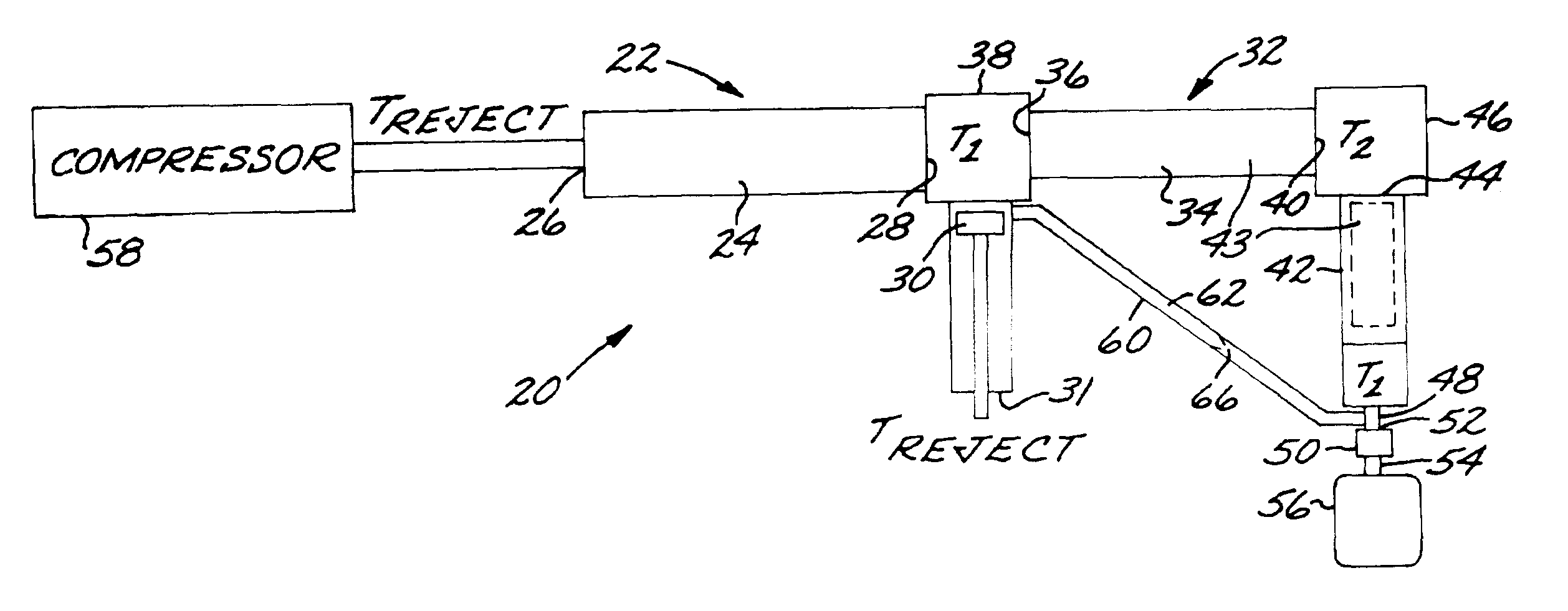
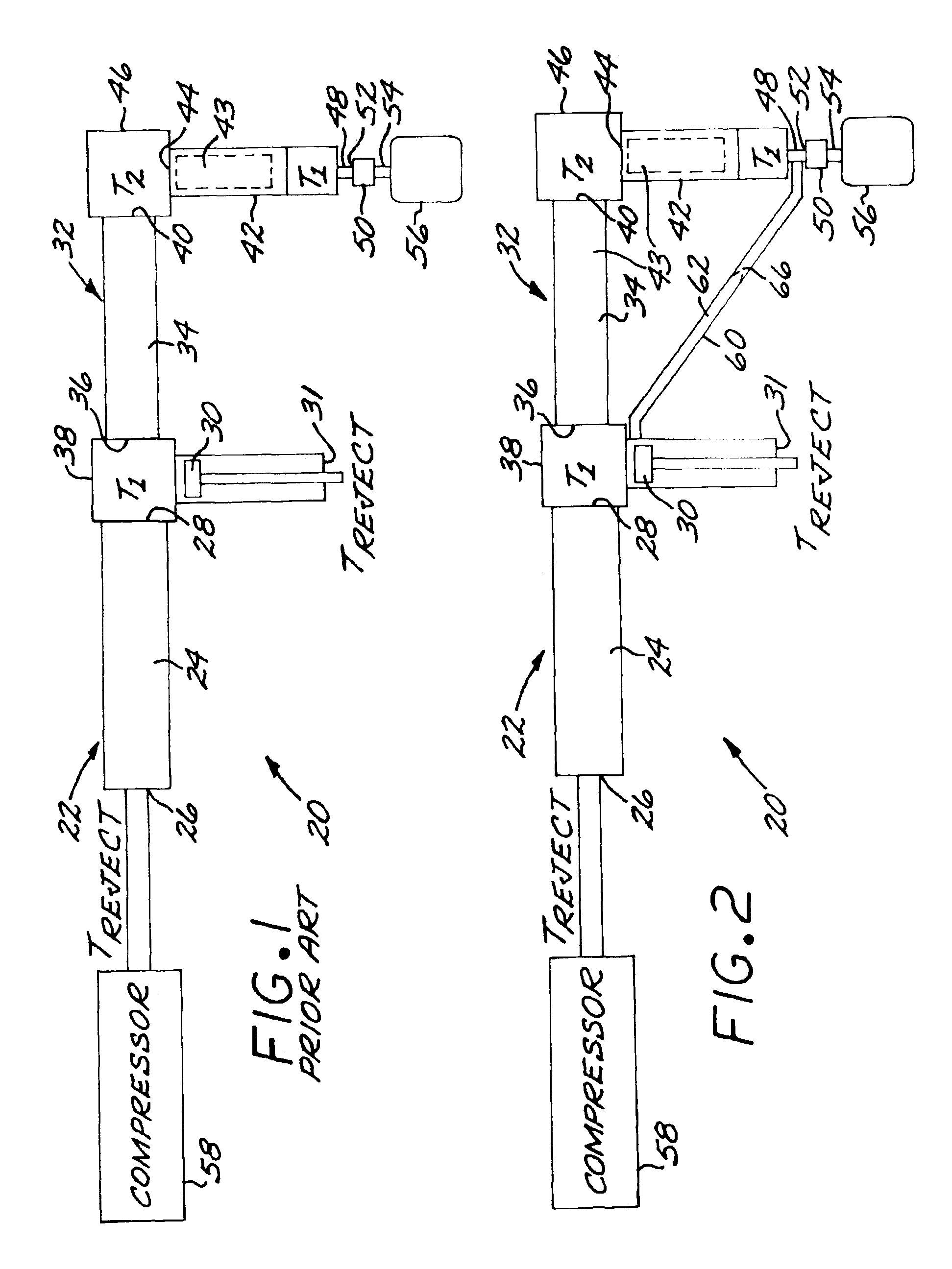
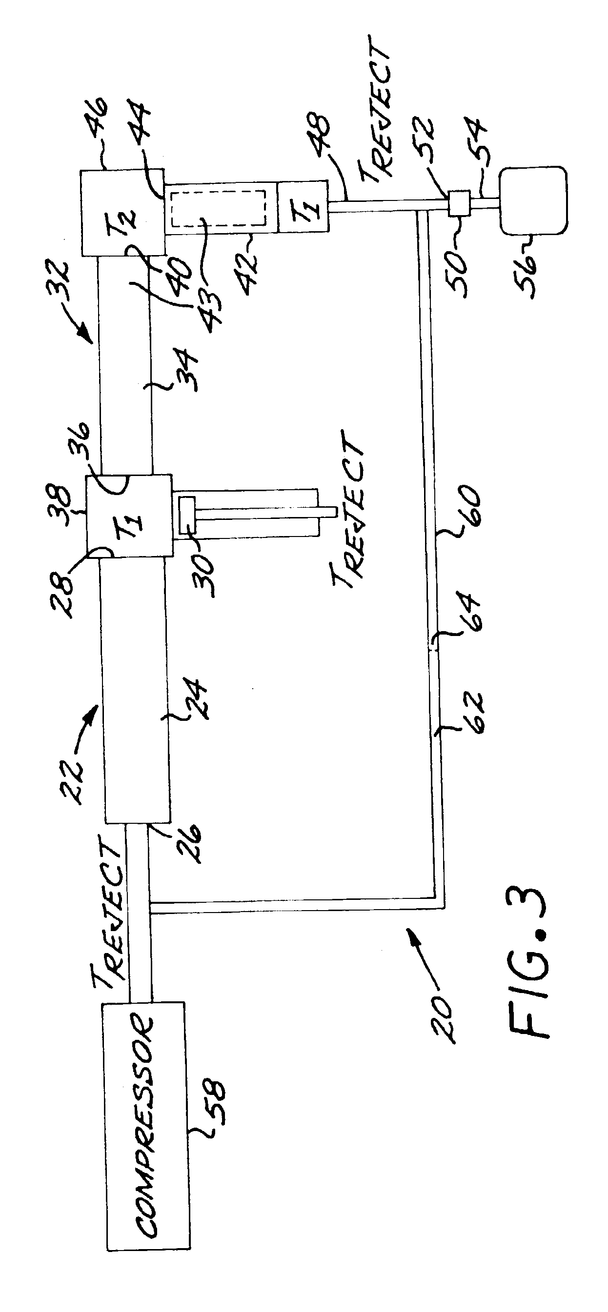
[0019]The physical structure of the two-stage Stirling / pulse tube cryocooler is described in detail in U.S. Pat. Nos. 6,167,707 and 6,330,800, whose disclosures are incorporated by reference. The preferred working gas for the two-stage Stirling / pulse tube cryocooler is helium. The schematic representations of the present FIGS. 1 and 2-3 illustrate this physical structure in a manner that is most conducive to understanding, respectively, the conventional approach and two embodiments of the present approach, in relation to the improvements of the present approach.

[0020]As seen in each of FIGS. 1-3, a two-stage hybrid cryocooler 20 comprises a first-stage Stirling expander 22. The first-stage Stirling expander 22 includes a first-stage regenerator 24 having a first-stage-regenerator inlet 26 and a first-stage regenerator outlet 28, and a driven Stirling expander piston 30. The first-stage-regenerator inlet 26 and a warm end 31 of the Stirling expander piston 30 are typically operated a...


PUM


Abstract

A two-stage hybrid cryocooler includes a first-stage Stirling expander having a first-stage regenerator having a first-stage-regenerator inlet and a first-stage-regenerator outlet, and a second-stage pulse tube expander. The second-stage pulse tube expander includes a second-stage regenerator having a second-stage regenerator inlet in gaseous communication with the first-stage regenerator outlet, and a second-stage regenerator outlet, and a pulse tube having a pulse-tube inlet in gaseous communication with the second-stage regenerator outlet, and a pulse-tube outlet. The second-stage regenerator and the pulse tube together provide a first gas-flow path between the first-stage regenerator and the pulse-tube outlet. A pulse tube pressure drop structure has a pulse-tube-pressure-drop inlet in gaseous communication with the pulse-tube outlet, and a pulse-tube pressure-drop outlet, and a gas volume is in gaseous communication with the pulse-tube pressure-drop outlet. A gas flow shunt provides gaseous communication between the first-stage regenerator and the pulse-tube outlet. The gas flow shunt provides a second gas-flow path between the first-stage regenerator and the pulse-tube outlet.

Description

[0001]This invention relates to a cryocooler and, more particularly, to a two-stage cryocooler whose performance is optimized through management of the gas flows in the refrigeration system.BACKGROUND OF THE INVENTION[0002]Some sensors and other components of spacecraft and aircraft must be cooled to cryogenic temperatures of about 77° K or less to function properly. A number of approaches are available to perform this cooling, including thermal contact to liquefied gases and cryogenic refrigerators, usually termed cryocoolers. The use of a liquefied gas is ordinarily limited to short-term missions. Cryocoolers typically function by the expansion of a gas, which absorbs heat from the surroundings. Intermediate temperatures in the cooled component may be reached using a single-stage expansion. To reach colder temperatures required for the operation of some sensors, such as about 40° K or less, a multiple-stage expansion cooler is often preferred. The present invention is concerned wi...

Claims


Application Information

Patent Timeline
Patent Type & Authority Patents(United States)
IPC IPC(8): F25B9/00F25B7/00F25B9/10F25B9/14
CPCF25B9/10F25B9/145F25B2309/14241F25B2309/1408F25B2309/003
Inventor PRICE, KENNETH D.KIRKCONNELL, CARL S.CICCARELLI, KEN J.
Owner RAYTHEON CO
Why Eureka
Try Eureka