
System And Insole For Measuring Information From The Foot Of A User And Related Method Of Providing Same

a technology for determining information and foot activity, applied in the field of systems for determining information regarding a foot and activity of a user, can solve the problems of inconvenient and unsightly wire connection of devices to measurement apparatuses, inability to readily be used with an athlete's existing footwear,

Inactive Publication Date: 2014-06-26
SMARTMOVE
View PDF9 Cites 62 Cited by
  • Summary
  • Abstract
  • Description
  • Claims
  • Application Information

AI Technical Summary

Benefits of technology

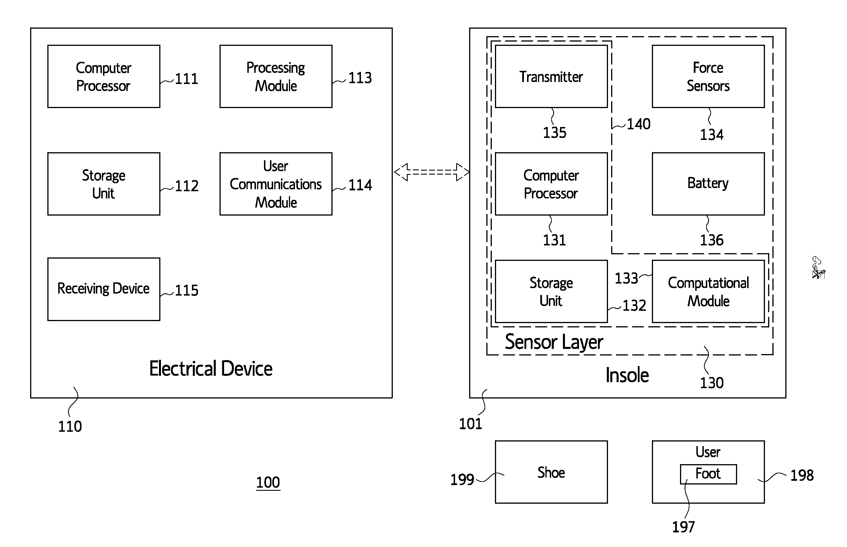
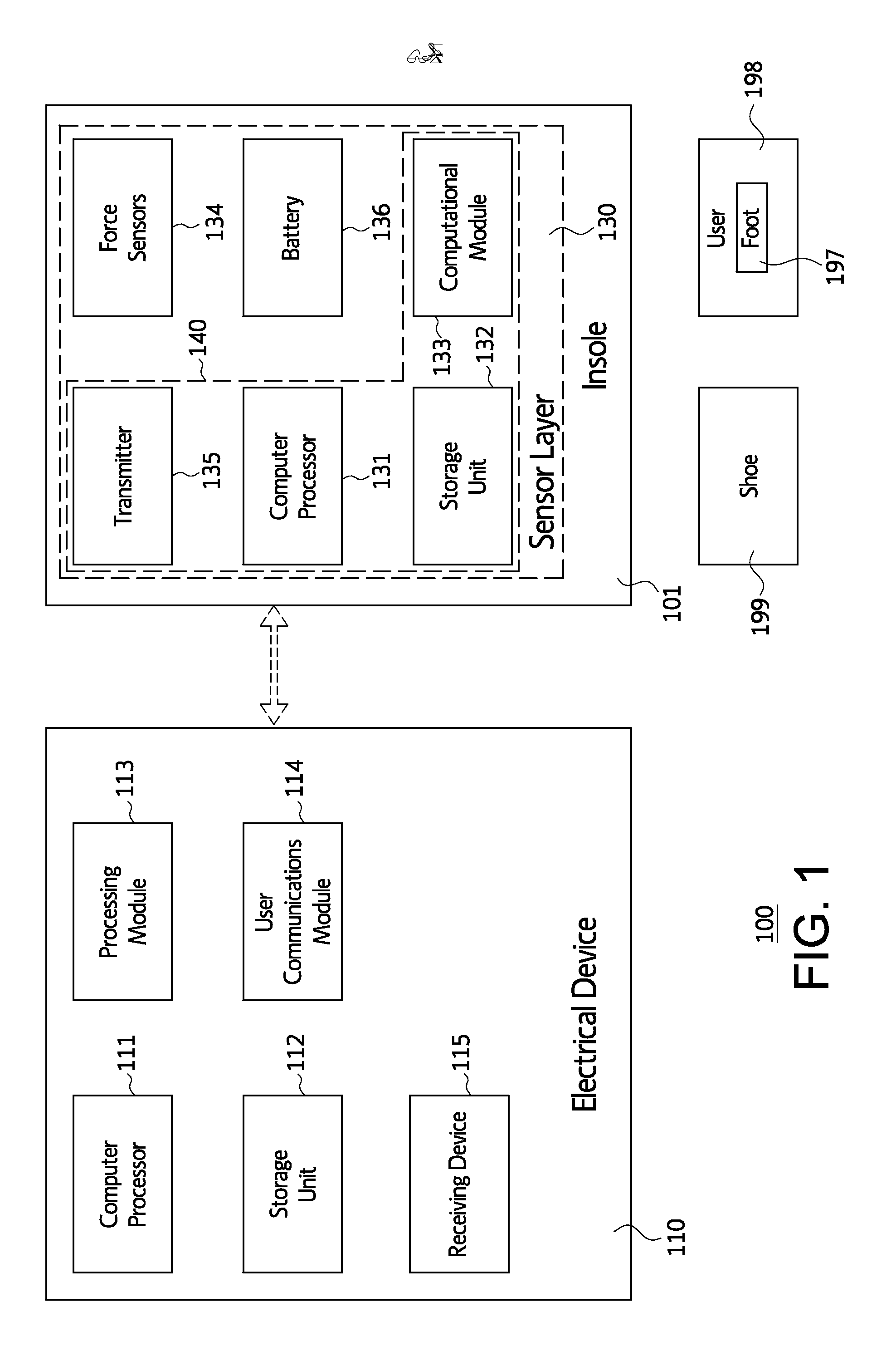
This patent describes a system for measuring information about a user's foot and activity using an insole. The insole includes a sensor that can communicate with a device to collect data about the user's foot. The system is unobtrusive and can be used with existing footwear. The invention solves the problem of previous devices that were bulky, required custom-made footwear, or lacked accurate measurements. The system can provide real-time information to the user and can be used in various sports and activities to improve performance and monitoring.

Problems solved by technology

However, these devices have various drawbacks.
Some devices require custom-built footwear to be constructed in order to measure forces caused by the foot, and cannot readily be used with an athlete's existing footwear.
Many devices require an inconvenient and unsightly wire connection to a measurement apparatus, which is either obtrusively worn on the body or which must be carried along to a new location every time the athlete moves.
In addition, various wireless measurement devices exist but these devices can be expensive and / or can lack reliable and accurate measurements.
Accordingly, a need or potential for benefit exists for an unobtrusive device capable of sensing a physical condition caused by a foot and communicating information regarding the foot to the user.

Method used


Image

  • System And Insole For Measuring Information From The Foot Of A User And Related Method Of Providing Same
  • System And Insole For Measuring Information From The Foot Of A User And Related Method Of Providing Same
  • System And Insole For Measuring Information From The Foot Of A User And Related Method Of Providing Same

Examples


Embodiment Construction

OF EMBODIMENTS

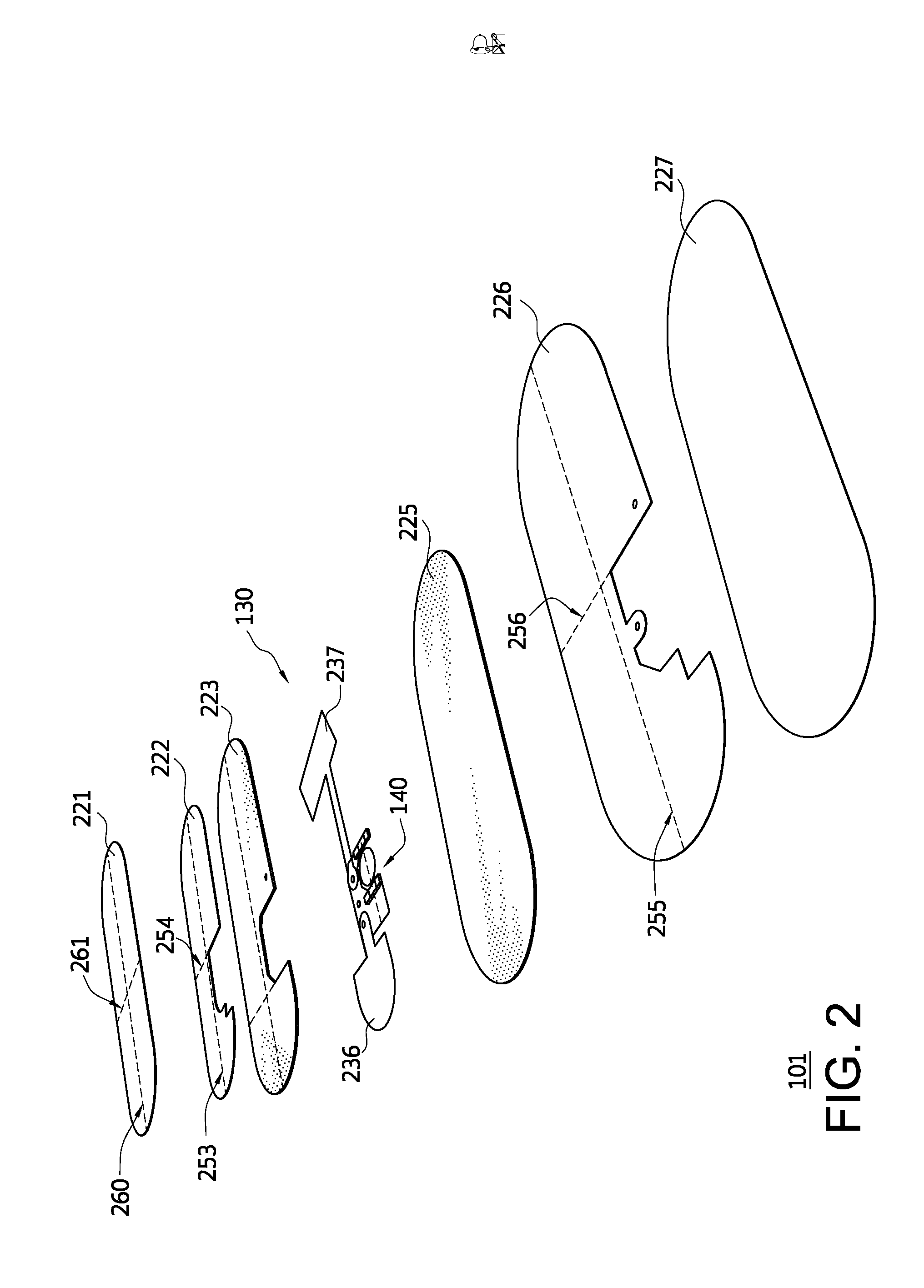
[0021]Some embodiments can concern an insole for a shoe to be worn on a foot of a user. The insole can include: an upper conductive ground plane layer; an upper compressible insulating layer physically coupled to the upper conductive ground plane layer; a conductive sensor layer physically coupled to the upper compressible insulating layer, the conductive sensor layer comprising one or more sensors that are configured to measure a force applied to the insole by the foot of the user; a lower compressible insulating layer physically coupled to conductive sensor layer; a lower conductive ground plane layer physically coupled to the lower compressible insulating layer and electrically coupled to the upper conductive ground plane layer; and at least one computational unit communicatively coupled to the one or more sensors. The upper conductive ground plane layer and the lower conductive ground plane layer are configured to substantially electrically shield the upper compres...


PUM


Abstract

An insole can include: an upper conductive ground plane layer; an upper compressible insulating layer physically coupled to the upper conductive ground plane layer; a conductive sensor layer physically coupled to the upper compressible insulating layer, the conductive sensor layer comprising one or more sensors are configured to a force applied to the insole by the foot; a lower compressible insulating layer physically coupled to conductive sensor layer; a lower conductive ground plane layer physically coupled to the lower compressible insulating layer and electrically coupled to the upper conductive ground plane layer; and at least one computational unit communicatively coupled to the one or more sensors. The upper conductive ground plane layer and the lower conductive ground plane layer are configured to substantially electrically shield the upper compressible insulating layer, the conductive sensor layer, and the lower compressible insulating layer from the shoe and the foot. Other embodiments are disclosed.

Description

CROSS-REFERENCE TO RELATED APPLICATIONS[0001]This application claims the benefit of U.S. Provisional Application No. 61 / 797,953, filed Dec. 20, 2012. U.S. Provisional Application No. 61 / 797,953 is incorporated herein by reference.STATEMENT REGARDING FEDERALLY SPONSORED RESEARCH OR DEVELOPMENT[0002]The U.S. Government has a paid-up license in this invention and the right in limited circumstances to require the patent owner to license other on reasonable terms as provided by the terms of 5R44DK083229-04 awarded by National Institutes of Health.FIELD OF THE INVENTION[0003]This invention relates generally to systems for determining information regarding a foot and activity of a user, and relates more particularly to insoles and systems for determining forces and other information related to the user and methods of providing the same.DESCRIPTION OF THE BACKGROUND[0004]In many sports and other activities, people find it useful to measure and analyze physical conditions caused by a foot in...

Claims


Application Information

Patent Timeline
Patent Type & Authority Applications(United States)
IPC IPC(8): A61B5/103
CPCA61B5/1036A61B5/1038A61B5/6807A61B2562/0252A43B17/00A43B3/34A43B3/44
Inventor CLARKE, ERICBARTLETT, DOUGLAS E.BAEVERSTAD, JR., HAROLD L.
Owner SMARTMOVE
Learn More