Retinal repair device and method

Active Publication Date: 2014-06-26
POWAY RETINAL TECH
View PDF4 Cites 14 Cited by
  • Summary
  • Abstract
  • Description
  • Claims
  • Application Information

AI Technical Summary

Benefits of technology

[0009]The above devices are primarily intended for use in treating retinal detachments in an office setting. Once the device is properly positioned to produce an indent or depression at the appropriate location, the fluid beneath the retina resorbs using the eye's natural retinal epithelial pigment pump, and the retina reattaches. The retina may then be tacked down using a laser to keep it from re-detaching. Alternatively, retinocryopexy may be applied to the retinal defect prior to insertion of the device. The de

Problems solved by technology

Surgical buckles as used in such surgeries can produce dis

Method used


Image

  • Retinal repair device and method
  • Retinal repair device and method
  • Retinal repair device and method

Examples


Example

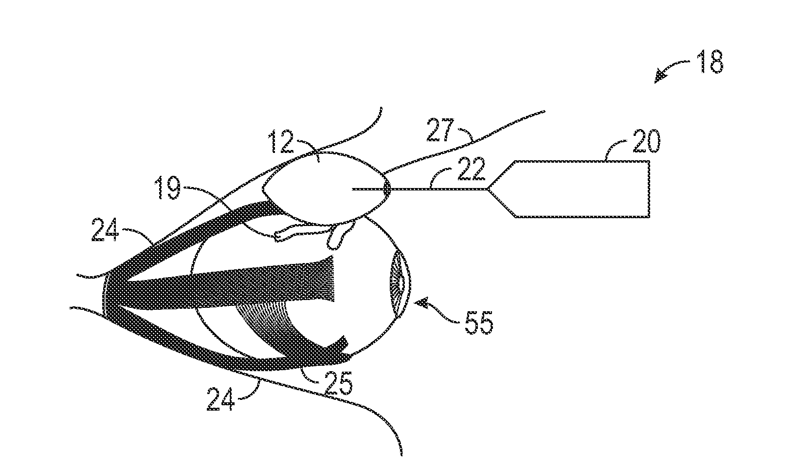
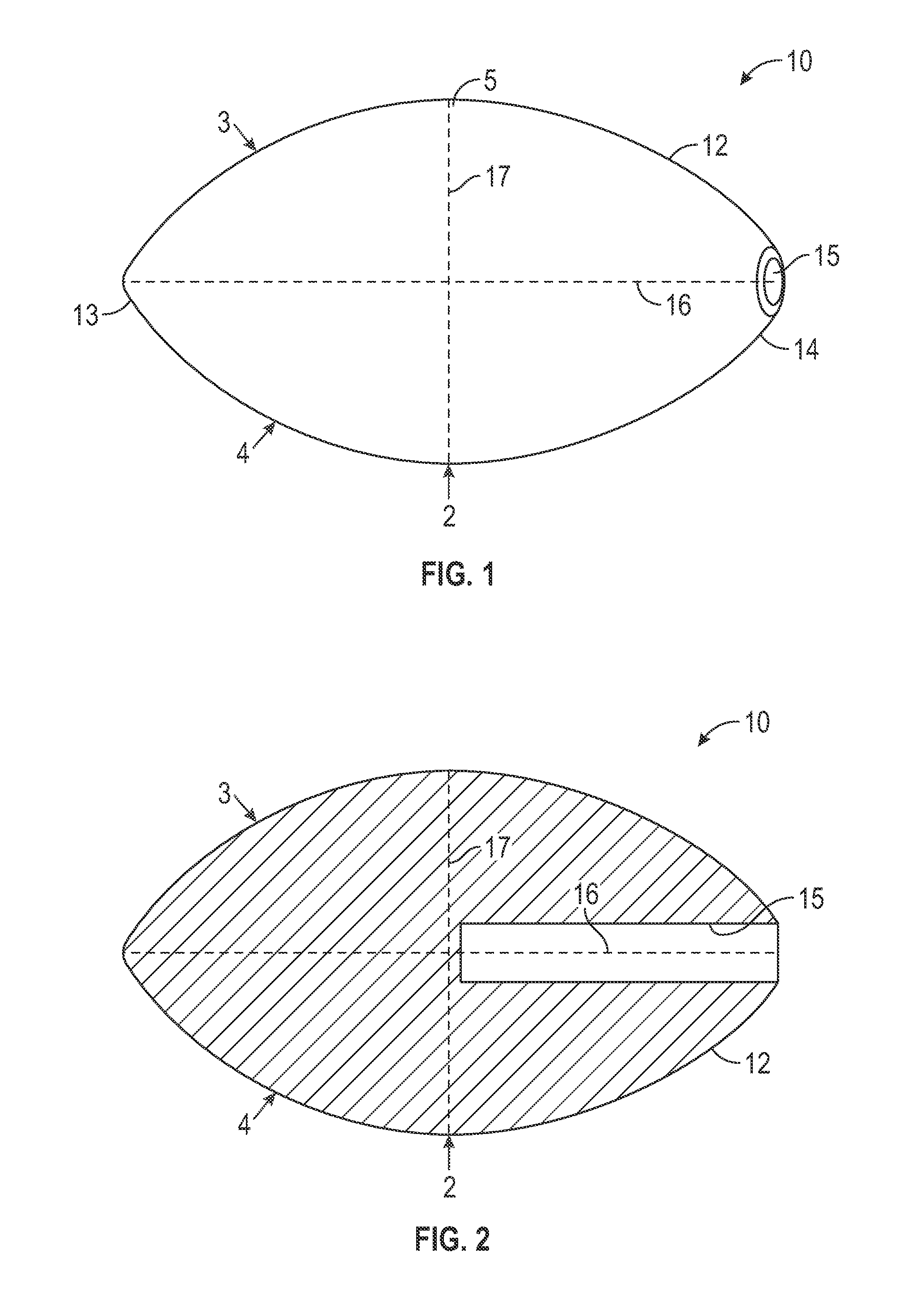
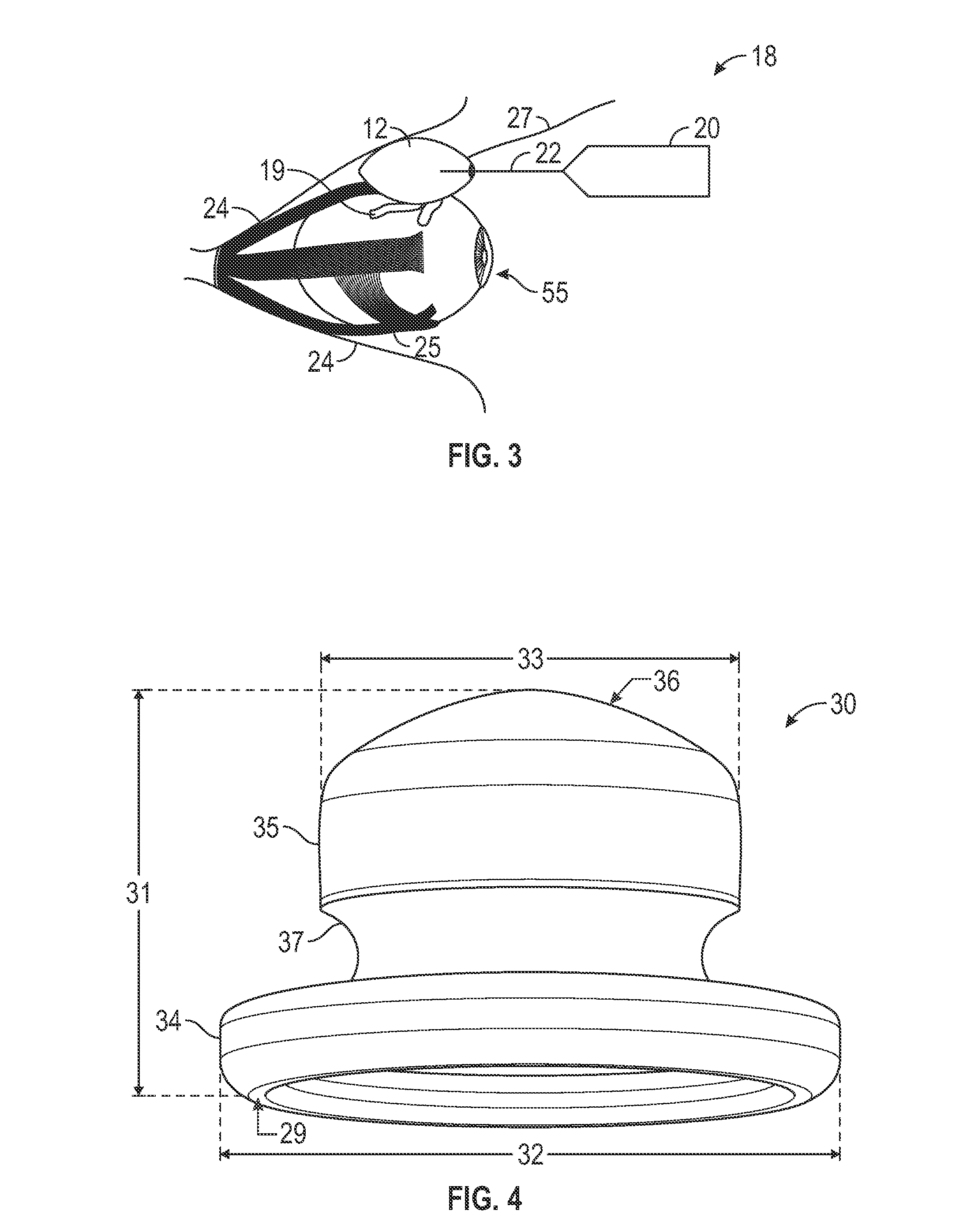
[0029]FIGS. 1 and 2 illustrate a first embodiment of a retinal repair device 10 comprising a member 12 including a posterior end 13 and an anterior end 14 opposite and distal to the posterior end 13. The member 12 may include an orbital facing surface 3 and a sclera facing surface 4, opposite the orbital facing surface 3. The member 12 may include a thickened portion 5 or a portion that is thickened to indent the sclera of an eye when the retina repair device is inserted into the periocular space, for example between the sclera and the orbital wall of the eye. The orbital facing surface 3 may be configured to contact the orbital wall of an eye. The thickened portion 5 may include a sclera contacting surface 2 that contacts and indents the sclera.

[0030]In the embodiment in FIGS. 1 and 2, the retinal repair device 10 may be a football-shaped or in the shape of a prolate spheroid. The orbital facing surface 3 and the sclera facing surface 4 may form the prolate spheroid shape. The thic...

Example

[0037]FIGS. 4 to 7 illustrate a retinal repair device 30 according to a second embodiment. In this embodiment, device 30 comprises a one piece molded member of a generally “top hat” shape, having an annular rim 34 and a cylindrical or thickened portion 35. Annular rim 34 may be a hollow cylinder with a closed end and an open end. The closed end is the end adjacent thickened portion 35. Annular rim 34 may include an orbital facing surface 29 at the open end. Orbital facing surface 29 may be configured to contact the orbital wall of an eye. The edges 38 and 39 of annular rim 34 may be rounded.

[0038]Thickened portion 35 is cylinder of solid cross-section extending axially from annular rim 34. Thickened portion 35 includes an end face or a sclera facing surface 36 distal to the annular rim 34 and the orbital facing surface 29. Sclera facing surface 36 may be outwardly rounded or part spherical, such as a spherical cap. At least a portion of sclera facing surface 36 may be a sclera conta...

Example

[0053]FIG. 13 illustrates a retinal repair device 300 according to a fourth embodiment. In this embodiment, device 300 includes an elongated portion 310 and a thickened portion 320 similar to those of device 100. The shapes lengths, widths, dimensions, and features of device 300 may be the same or similar to those of device 100. Elongated portion 310 also includes a posterior end 311, an anterior end 312, an orbital facing surface 313, and a sclera facing surface 314, located opposite the orbital facing surface 313. In the embodiment illustrated in FIG. 13, posterior end 311 includes a flat surface with rounded edges between posterior end 311 and orbital facing surface 313, and posterior end 311 and sclera facing surface 314.

[0054]In the embodiment illustrated in FIG. 13, thickened portion 320 includes protrusion 322 extending from sclera facing surface 314 and is cylindrically shaped, such as a half cylinder. Device 300 includes a first wing 325 and a second wing 326 extending from...


PUM


Abstract

A device which may be formed of suitable elastomeric, biocompatible material is configured to be wedged into Tenon's space between the orbital and scleral walls of the eye at the location of a retinal tear or break. When positioned, the device pushes the eye wall inward to close the tear, and fluid below the retinal wall resorbs.

Description

RELATED APPLICATIONS[0001]This application claims the benefit of U.S. provisional application Ser. No. 61 / 721,081, filed Nov. 1, 2012, titled “RETINAL REPAIR DEVICE AND METHOD,” which is hereby incorporated by reference.BACKGROUND[0002]1. Field of the Invention[0003]The present invention relates generally to repair devices and methods for retinal tears and detachments, and is particularly concerned with non-inflatable retinal repair devices.[0004]2. Related Art[0005]Retinal detachment or separation can occur spontaneously, or due to myopia, cataract surgery, certain eye diseases, and long term medical conditions such as diabetes. Detachment occurs when vitreous liquid leaks through a retinal opening or tear and accumulates under the retina. As liquid accumulates, the retina may separate from the underlying layer, the retinal pigment epithelium. Normally, surgery is used to repair retinal tears, holes and detachments. In this type of surgery, known as scleral buckling, a device is at...

Claims


Application Information

Patent Timeline
IPC IPC(8): A61F2/14
CPCA61F9/00727A61F2/14
Inventor TORNAMBE, PAUL E.MCKINNEY, R. TODDFITZGERALD, PATRICK J.BENKE, JASPERSIMPSON, JOHN A.
Owner POWAY RETINAL TECH
Why Eureka
Try Eureka