Thermal Barrier For Building Foundation Slab

a technology of insulation device and building foundation, which is applied in the direction of foundation engineering, heat-proofing, building components, etc., can solve the problems of higher heating cost and cold floors, and achieve the effect of reducing heat loss through the top or bottom perimeter and reducing heat loss

Inactive Publication Date: 2014-07-03
TB HLDG LLC
View PDF9 Cites 30 Cited by
  • Summary
  • Abstract
  • Description
  • Claims
  • Application Information

AI Technical Summary

Benefits of technology

[0011]A first advantage of the present invention is that when installed it provides an R-value of at least about 5 inch of apparatus thickness. A second advantage of the present invention is that when installed it provides a U-value of at most about 0.20 inch of apparatus thickness. An additional advantage of the present invention is that when installed it provides a reduction in heat loss through the slab of at least about 20% and as much as over 60%.
[0012]In a second exemplary embodiment, the present invention comprises a prefabricated thermal barrier comprising a slab foundation set on a footer, said thermal barrier comprising: a footer insulating member, said footer insulating member disposed horizontally adjacent to the top of a footer, said footer insulating member comprising a generally cuboid shape having: an elongated top side and an elongated bottom side, wherein said bottom side and said top side are parallel; a pair of generally parallel front and rear sides; and at least one vertically oriented void between said parallel top and bottom portion, said void suitable for a structural material to pass through; an interior insulating member, said interior insulating member disposed vertically against a vertical wall of the footer, said interior insulating member extending downward from said footer insulating member, said interior vertical insulating member generally in physical contact with said footer insulating member; and an exterior insulating member, said exterior insulating member disposed at about the front side of the footer insulting member, such that: said exterior insulating member is adjacent to the exterior of a building; and such that the exterior insulating member extends vertically upward from said footer insulating member; and such that said exterior insulating member is generally parallel to said interior insulating member; and such that said exterior insulating member is generally in physical contact with said footer insulating member.
[0013]Advantageously, this second embodiment provides a continuous thermal barrier at the side of the slab and between the bottom of the slab and the footer for the foundation.
[0014]Again, an advantage of the present invention is that when installed it provides an R-value of at least about 5 inch of apparatus thickness between the slab and ambient conditions. A second advantage of the present invention is that when installed it provides a U-value of at most about 0.20 inch of apparatus thickness between the slab and ambient conditions. An additional advantage of the present invention is that when installed it provides a reduction in heat loss through the top or bottom perimeter of the slab.

Problems solved by technology

Another reason is cost.
However, in colder climates, where the ground freezes in the winter, use of an non-insulated slab results in cold floors and higher heating costs as heat is lost from the home to the outside.

Method used


Image

  • Thermal Barrier For Building Foundation Slab
  • Thermal Barrier For Building Foundation Slab
  • Thermal Barrier For Building Foundation Slab

Examples


Embodiment Construction

[0024]The following detailed description is merely exemplary in nature and is not intended to limit the described embodiments or the application and uses of the described embodiments. As used herein, the word “exemplary” or “illustrative” means “serving as an example, instance, or illustration.” Any implementation described herein as “exemplary” or “illustrative” is not necessarily to be construed as preferred or advantageous over other implementations.

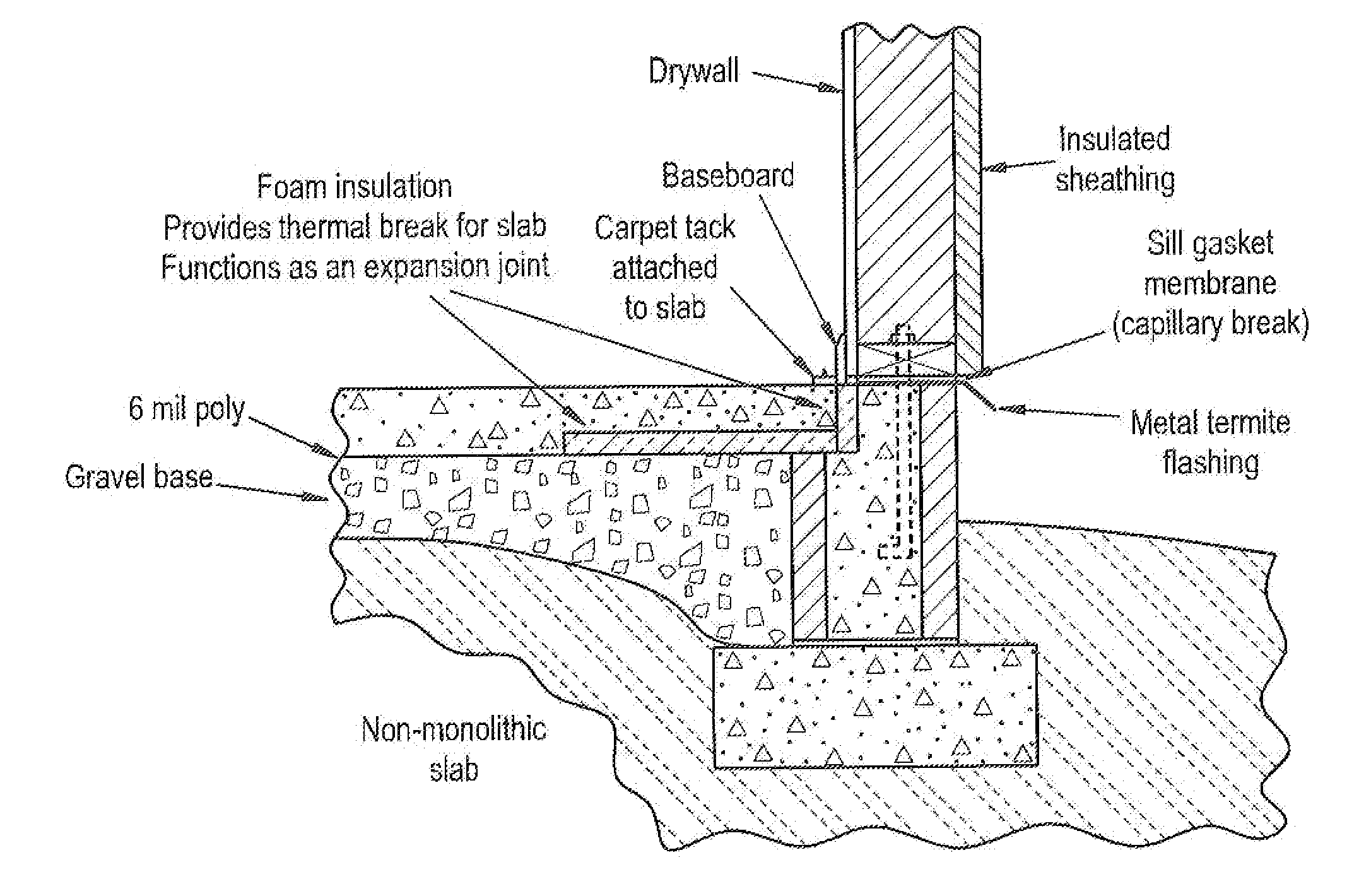
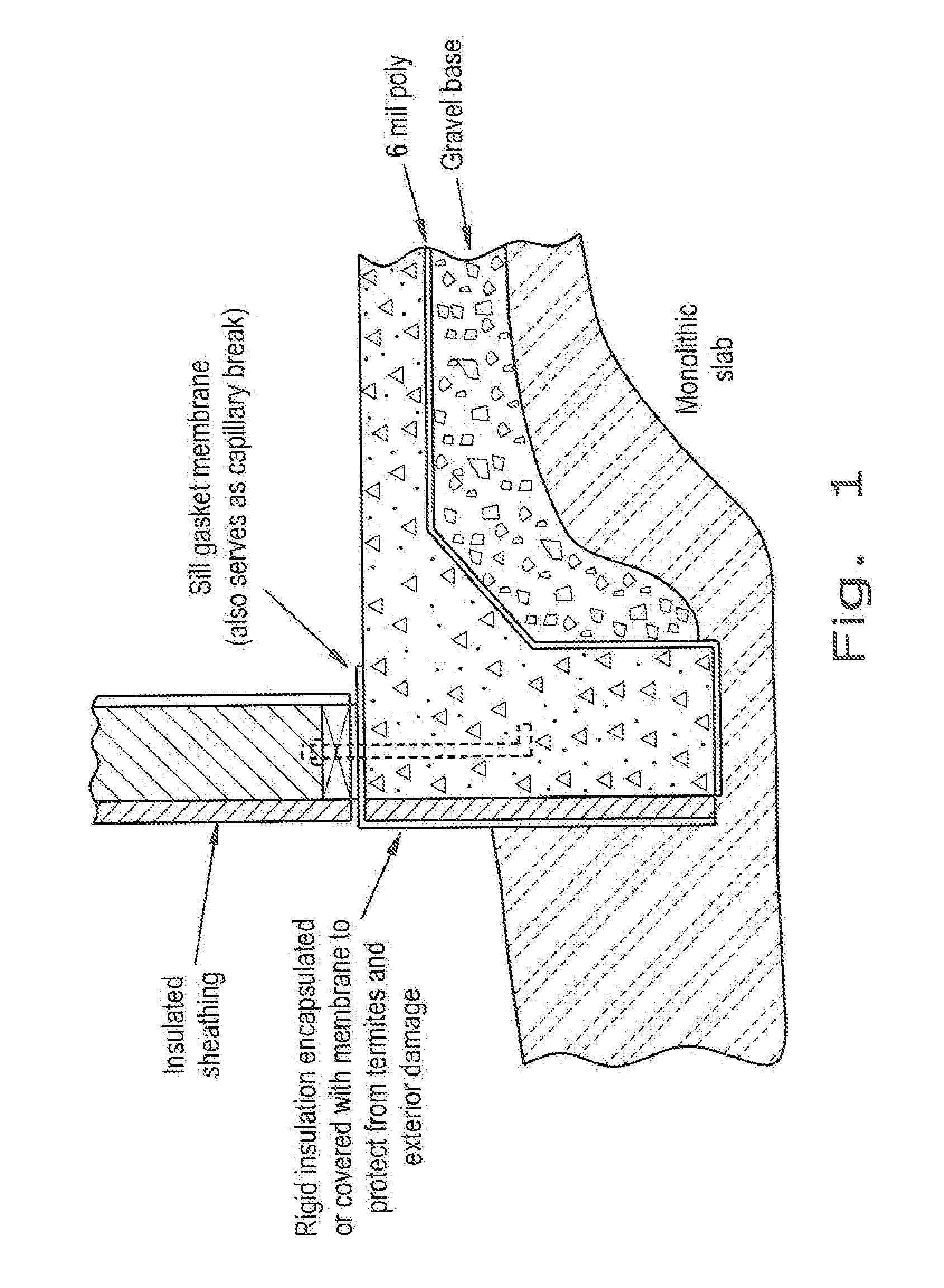
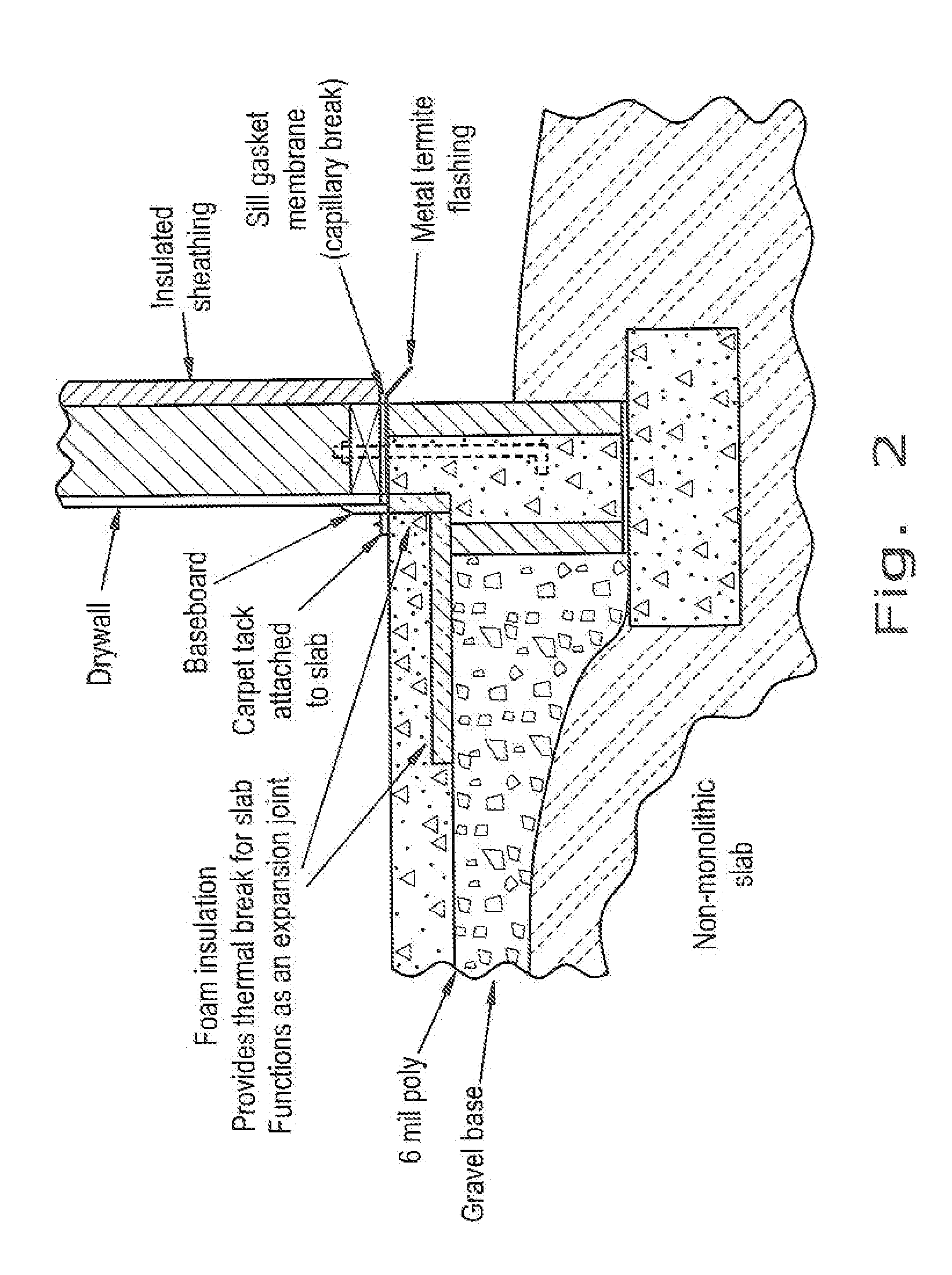
[0025]All of the implementations described below are exemplary implementations provided to enable persons skilled in the art to make or use the embodiments of the disclosure and are not intended to limit the scope of the disclosure, which is defined by the claims. In the present description, the terms “upper”, “lower”, “left”, “rear”, “right”, “front”, “vertical”, “horizontal”, and derivatives thereof shall relate to the invention as oriented in FIG. 1.

[0026]Furthermore, there is no intention to be bound by any expressed or implied th...


PUM

PropertyMeasurementUnit
perimeteraaaaaaaaaa
thickaaaaaaaaaa
thicknessaaaaaaaaaa

Abstract

A thermal barrier for reducing heat transfer through the slab foundation of a building, said thermal barrier comprising: a substrate; a first attachment means disposed at the top of said substrate for attaching said thermal barrier to a building; an insulating sheathing attached to said substrate; a reflective layer disposed between said sheathing and said substrate; and a second attachment means for attaching said apparatus to a building, said second attachment means disposed adjacent to one side of said sheathing and against said substrate.

Description

FIELD OF THE INVENTION[0001]This invention is related to building construction. More particularly, this invention is an insulation device for slab foundations of residential and commercial buildings.BACKGROUND OF THE INVENTION[0002]Most residential and smaller commercial buildings in the United States are built using standardized building practices. One reason for this consistency is a set of uniform building codes that apply across the country. Another reason is cost. The techniques used to build homes, for example, produce reliable structures quickly at relatively low cost. Homes in the United States are generally built using the following procedure: grading and site preparation, foundation construction, framing, window and door installation, roofing, siding, electrical, plumbing, HVAC, insulation, drywall, underlayment, trim, and interiors.[0003]One of the first steps in erecting a residential or commercial building is constructing a foundation. Houses, for example, are generally...

Claims


Application Information

Patent Timeline
Patent Type & Authority Applications(United States)
IPC IPC(8): E04B1/80E02D31/00
CPCE04B1/80E02D31/00E02D27/02E04B1/72E04B2001/7679E04B2001/7691E04B2103/04
Inventor HICKS, TONY
Owner TB HLDG LLC
Why Eureka
Try Eureka