
Parameterizing a 3D modeled object for tessellation

a three-dimensional model and object technology, applied in the field of computer programs and systems, can solve the problems of large memory consumption, discretization problems, and the inability of the gpu to display the surface provided as a b-rep directly

Active Publication Date: 2014-07-03
DASSAULT SYSTEMES
View PDF2 Cites 37 Cited by
  • Summary
  • Abstract
  • Description
  • Claims
  • Application Information

AI Technical Summary

Benefits of technology

The patent describes a computer-implemented method for parameterizing and tessellating a three-dimensional modeled object. The method involves creating a boundary representation of the object using geometrical data and topological data, and then creating 2D meshes that fit the boundary representation. The 2D meshes are then associated with the geometrical data. The method also involves subdividing the boundary edges of the object into parametric arcs and defining a partition of the object using these arcs. The 2D meshes are determined based on the position of vertices on the parametric surfaces. The method can be used in computer software and computer systems. The technical effects of the patent include improved efficiency and accuracy in parameterizing and tessellating three-dimensional objects.

Problems solved by technology

However, a GPU cannot display a surface provided as a B-Rep directly.
Approximating smooth surfaces with flat geometry leads to discretization problems.
This is a well-known problem in CAD applications.
Static tessellation produces a heavy mesh with an average accuracy for vertices and normals and consumes huge memory for high curvature models, which is an issue when the approximate model is placed on persistent memory.
Another issue with static tessellation appears when the accuracy needs to be increased.
First of all, this is not always possible, because the exact model may have been previously discarded.
Indeed, the exact model usually consumes a lot of memory space and may either be deleted, or discarded when the designer wants to send the modeled object elsewhere, e.g. for displaying and / or for geometric operations, e.g. to another user and / or another client system.
Second of all, in cases that the exact model is nevertheless kept, an issue is that, when demanding a higher accuracy, the tessellation has to be performed from scratch, i.e. from the exact model of the surface.
This takes a lot of time.
However, PNT tessellation also presents issues.
For example, the possibility to increase accuracy (without using the initial exact model, which may have been discarded) still has a limit, because the base mesh is only an approximation of the initial surface.
Furthermore, the base mesh approximates the surface in terms of positions, but computing normal vectors from the base mesh may prove relatively inaccurate.
As a result, visualization artifacts happen while rendering the final mesh.
For instance, surface representation and shading are deteriorated.
The existing solutions mentioned above thus lack efficiency.

Method used


Image

  • Parameterizing a 3D modeled object for tessellation
  • Parameterizing a 3D modeled object for tessellation
  • Parameterizing a 3D modeled object for tessellation

Examples


Embodiment Construction

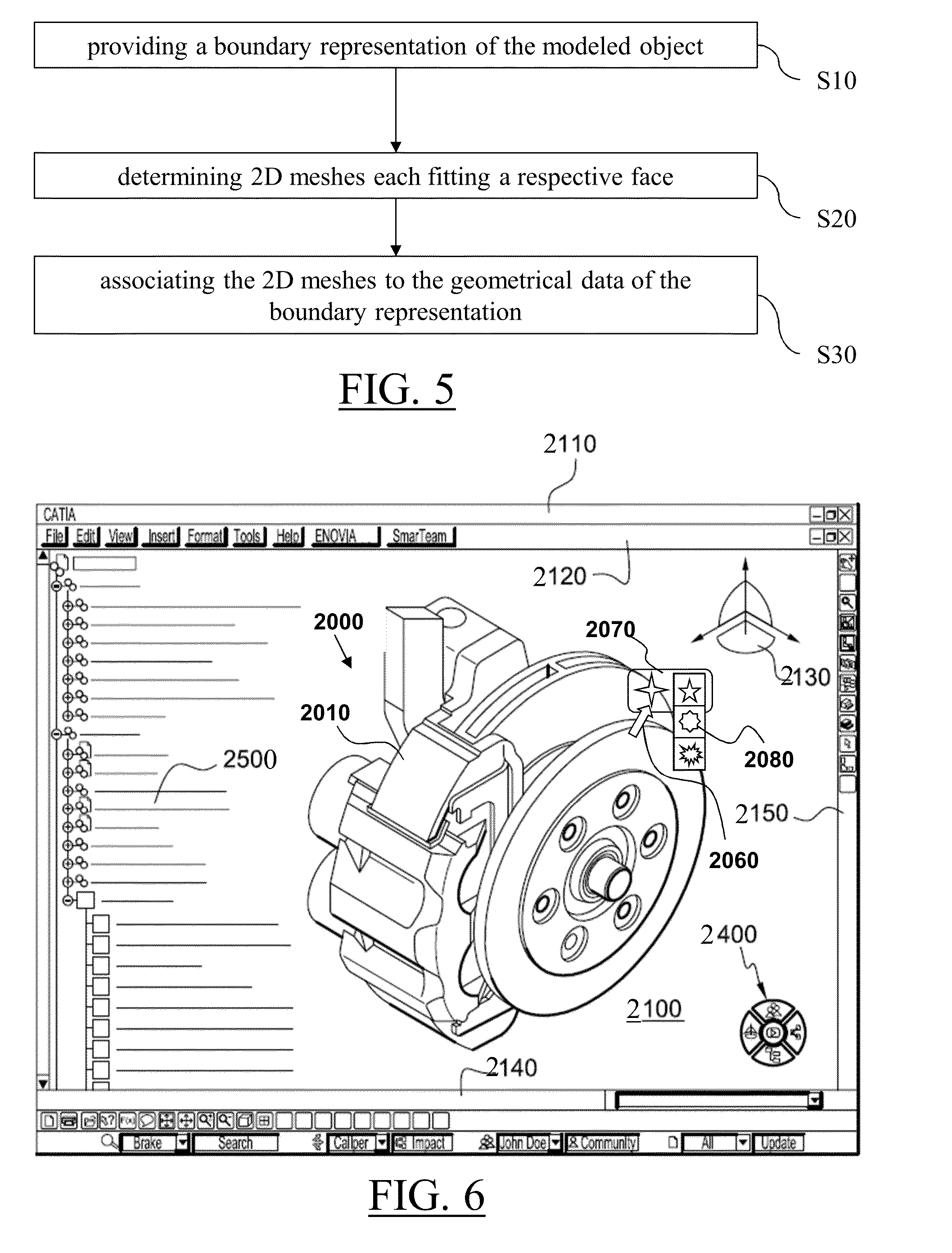
[0053]FIG. 5 shows a flowchart of an example of the computer-implemented method for parameterizing a three-dimensional modeled object for tessellation. The method comprises the step of providing S10 a boundary representation of the modeled object. The boundary representation comprises both geometrical data and topological data. The geometric data include parametric surfaces. The topological data include a set of faces. Each face is defined as a portion of the 2D domain of a respective parametric surface. The method also comprises the step of determining S20 2D meshes each fitting a respective face. And the method also comprises the step of associating S30 the 2D meshes to the geometrical data of the boundary representation.

[0054]Such a method improves the tessellation of a 3D modeled object. The parameterizing of the modeled object before the tessellation allows a faster tessellation, relatively to the case that the tessellation is performed from the raw data constituting the bounda...


PUM


Abstract

It is proposed a computer-implemented method for parameterizing a three-dimensional modeled object for tessellation. The method comprising the steps of providing a boundary representation of the modeled object, the boundary representation comprising geometrical data including parametric surfaces and topological data including a set of faces each defined as a portion of the 2D domain of a respective parametric surface; determining 2D meshes each fitting a respective face; and associating the 2D meshes to the geometrical data of the boundary representation. Such a solution improves the tessellation of a 3D modeled object.

Description

RELATED APPLICATION(S)[0001]This application claims priority under 35 U.S.C. §119 or 365 to European Patent Application No. 12306696.1 filed on Dec. 28, 2012. The teachings of the foregoing application are herein incorporated in their entirety.FIELD OF THE INVENTION[0002]The invention relates to the field of computer programs and systems, and more specifically to a method, system and program for parameterizing a three-dimensional modeled object for tessellation and / or for tessellating a three-dimensional modeled object parameterized for tessellation.BACKGROUND[0003]A number of systems and programs are offered on the market for the design, the engineering and the manufacturing of objects. CAD is an acronym for Computer-Aided Design, e.g. it relates to software solutions for designing an object. CAE is an acronym for Computer-Aided Engineering, e.g. it relates to software solutions for simulating the physical behavior of a future product. CAM is an acronym for Computer-Aided Manufactu...

Claims


Application Information

Patent Timeline
IPC IPC(8): G06T17/20
CPCG06T17/20G06T17/30G06T17/10
Inventor QUILOT, LAURENTFEKI, ABDELMONEMPHUNG, TUAN ANHROUDIL, DANIEL
Owner DASSAULT SYSTEMES
Learn More