

Pneumatic tire
Active Publication Date: 2014-07-10
SUMITOMO RUBBER IND LTD
View PDF10 Cites 26 Cited by
- Summary
- Abstract
- Description
- Claims
- Application Information
AI Technical Summary
Benefits of technology
[0006]The present invention has been worked out in light of the circumstances described above, and has a main object of providing a pneumat
Problems solved by technology
However, the large deformation of block-pieces causes loss of ground contact area of the tread block, where
Method used
View moreImage
Smart ImageViewing Examples

Examples
 PUM
 Abstract
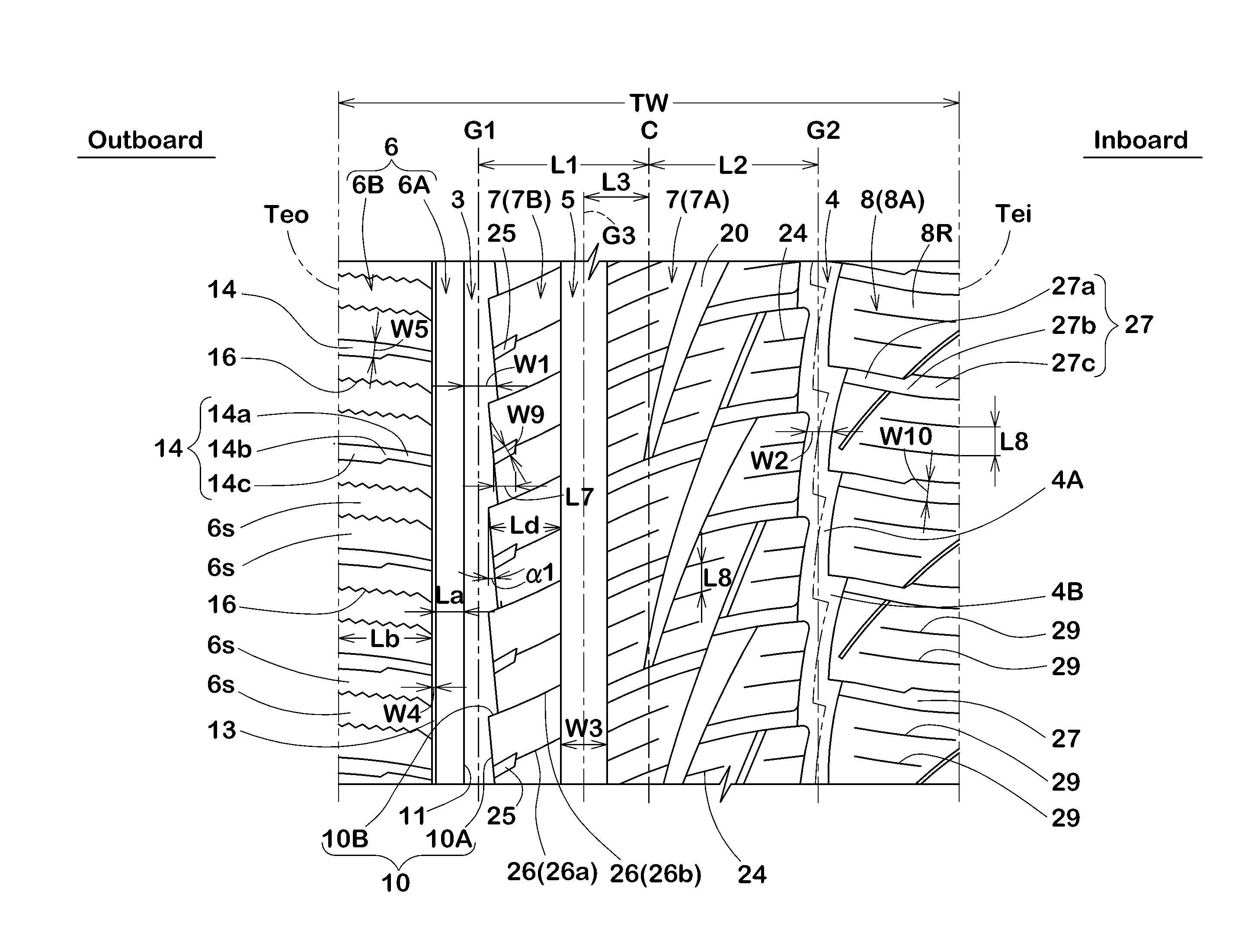
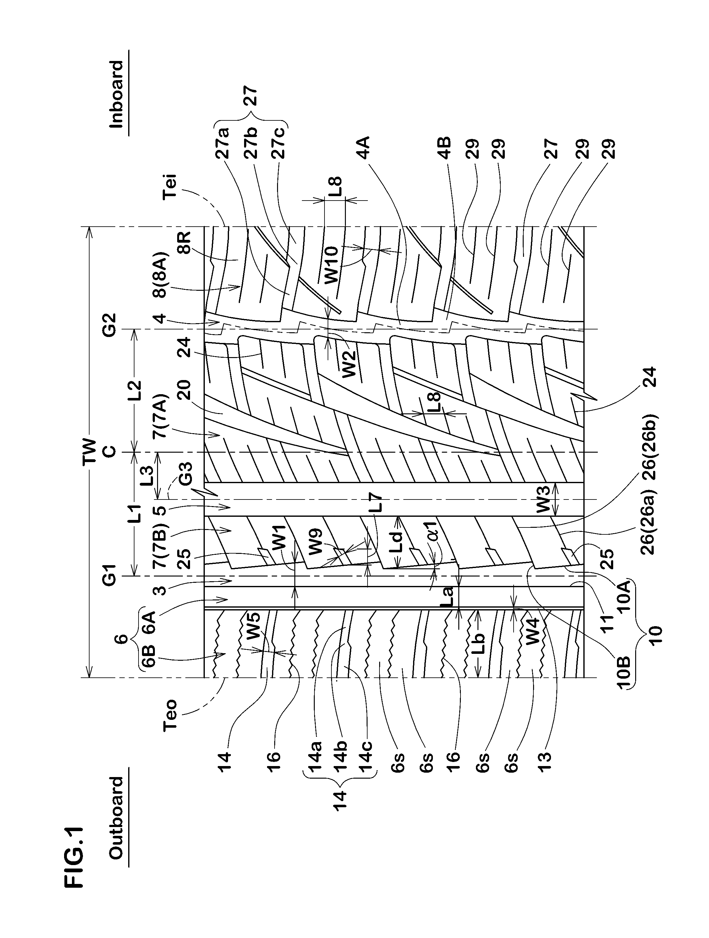
A pneumatic tire includes a tread portion with an asymmetric pattern including an outboard shoulder main groove, an inboard shoulder main groove, an outboard shoulder portion between the outboard shoulder main groove and an outboard tread edge, a middle portion between the outboard shoulder main groove and the inboard shoulder main groove, and an inboard shoulder portion between the inboard shoulder main groove and an inboard tread edge, wherein the outboard shoulder portion is provided with a three dimensional sipe that has a pair of sipe surfaces extending to a depth direction of the sipe while changing its direction or opening configuration, and the inboard shoulder portion or the middle portion is provided with a two dimensional sipe that has a pair of sipe surfaces extending to a depth direction of the sipe while maintaining its direction and opening configuration.
Description
BACKGROUND OF THE INVENTION[0001]1. Field of the Invention[0002]The present invention relates to a pneumatic tire that offers an improved traveling performance on an icy road while maintaining steering stability on a dry road and wear resistance.[0003]2. Description of the Related Art[0004]In order to improve traveling performance on a icy road, Japanese patent application laid-open No. 2011-162022 discloses a pneumatic tire having a tread block provided with two dimensional sipes that divide the tread block into a plurality of block-pieces with edges for scratching the icy road surface. Typically, the two dimensional sipe comprises a pair of sipe surfaces each of which uniformly extends to a bottom of the sipe while keeping its direction and opening configuration. The adjacent block-pieces divided by the two dimensional sipe are usually easy to deform each other through the sipe surfaces when the tire is subjected to friction force on the road, such that each edge of the block-piec...
Claims
Login to View More Application Information
Patent Timeline
 IPC IPC(8): B60C11/03B60C11/12
CPCB60C11/12B60C11/0304B60C11/1218B60C11/1236B60C2011/0346B60C2011/0348B60C2011/0374B60C2011/0395B60C11/04B60C2011/0381B60C2011/1227
InventorTAKEMOTO, YOSHIAKI
OwnerSUMITOMO RUBBER IND LTD