Electric vehicle

a technology of electric vehicles and traction motors, applied in the direction of electric devices, process and machine control, instruments, etc., can solve the problems of driver discomfort, vehicle operation may be corrected, and the torque output characteristics of the left and right traction motor units may differ, etc., to achieve the effect of simple configuration

Active Publication Date: 2015-01-08
NTN CORP
View PDF2 Cites 17 Cited by
  • Summary
  • Abstract
  • Description
  • Claims
  • Application Information

AI Technical Summary

Benefits of technology

[0019]In the present invention, in case of including a turning device 10 configured to be driven or auxiliarily driven by the turning motor 14, the steering torque detector 19 may obtain the information of the steering torque Ts by converting a current of the turning motor 14. When the steering angle θs is at the neutral position, if a driving force difference has occurred between the left and right drive wheels 2, 2, the torque of the turning motor 14 is increased due to a load acting on the wheels 3, 3 from the road surface. The torque of the turning motor 14 can be obtained from the current thereof. As a result, the information of the steering torque Ts is obtained by converting the current in the turning motor 14, and thus the information of the steering torque Ts can be obtained with a simple configuration in which an ammeter and a converter are merely provided.

Problems solved by technology

In addition, a difference may occur between the torque output characteristics of the left and right traction motor units due to aging of each traction motor unit.
If amounts of output torque of the respective left and right traction motor units are significantly different from each other, a difference occurs between a vehicle behavior intended by the driver and an actual vehicle behavior, so that the driver feels uncomfortable.
In addition, the problem also arises that correction of a vehicle operation by the driver may be required.

Method used


Image

  • Electric vehicle
  • Electric vehicle
  • Electric vehicle

Examples


Embodiment Construction

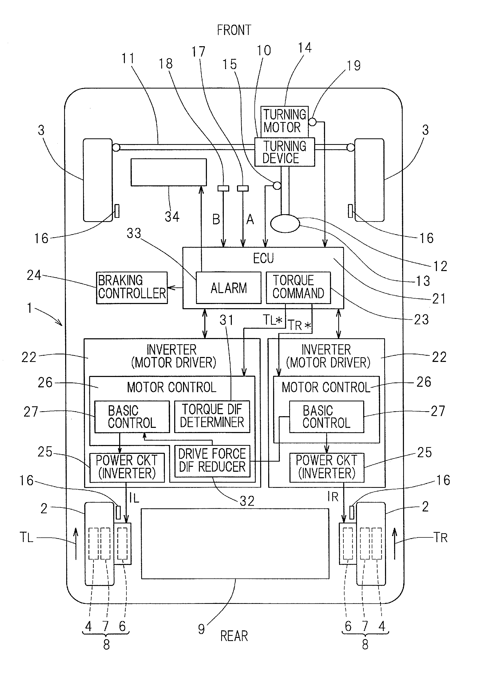
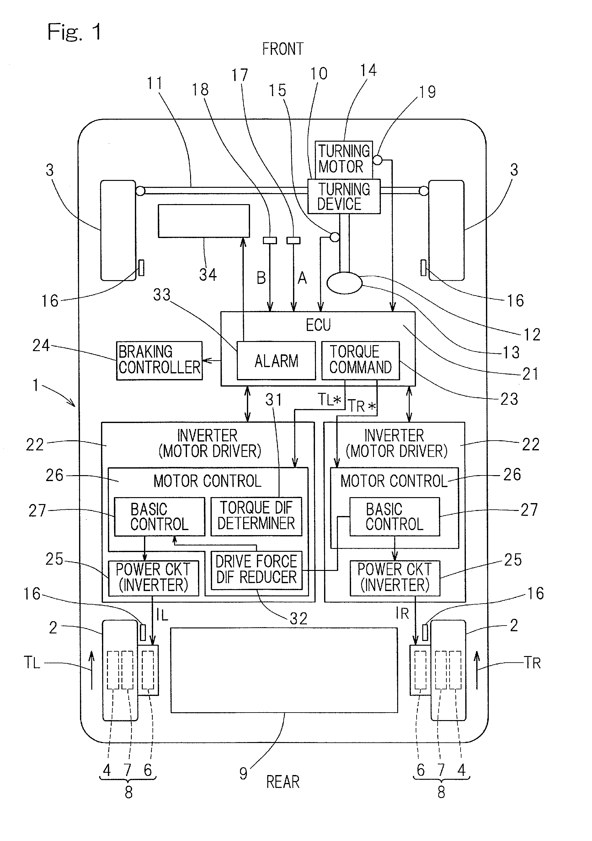
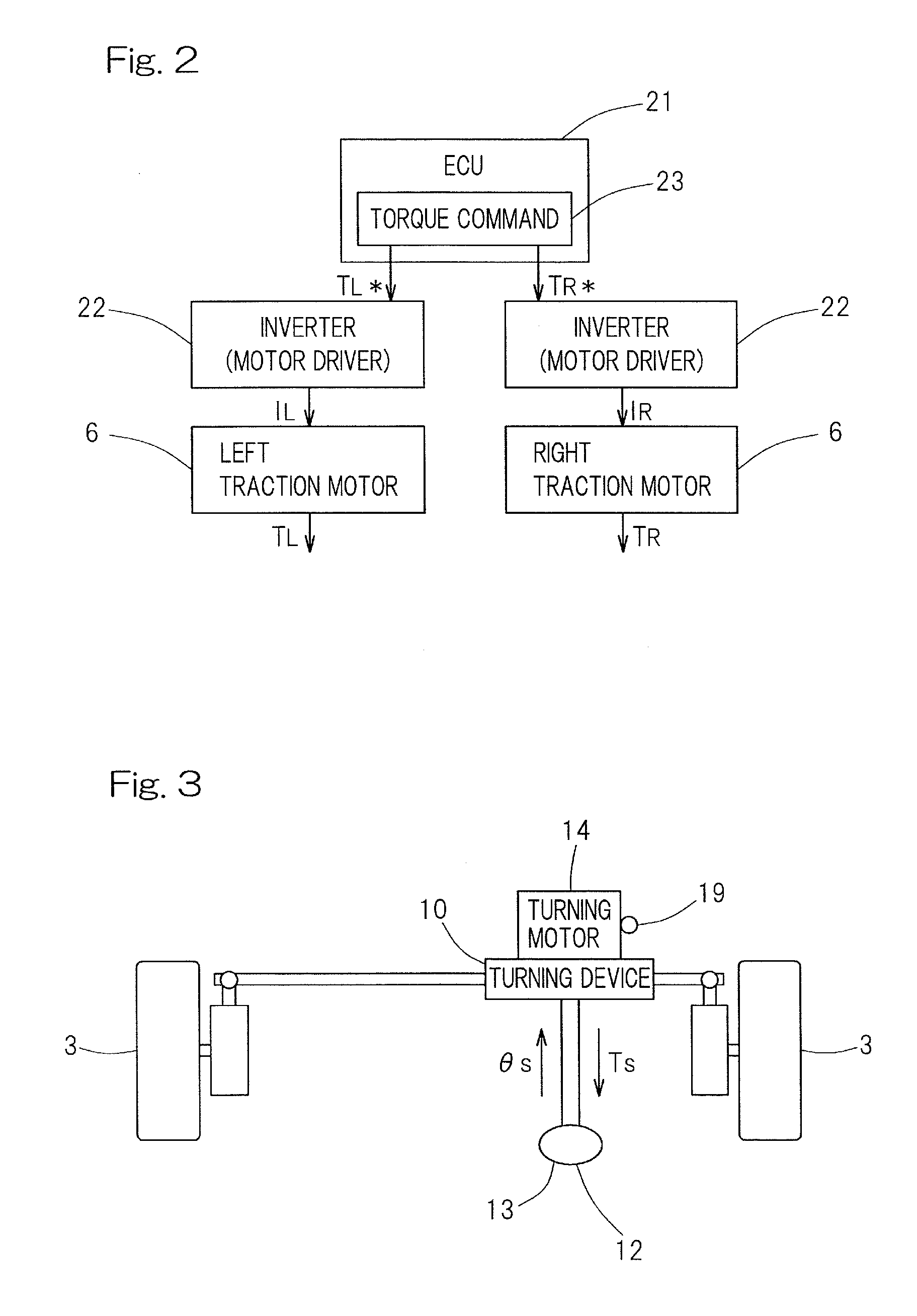
[0032]An embodiment of the present invention will now be described in connection with FIG. 1 to FIG. 6. The electric vehicle such as shown in FIG. 1 may be a four-wheel vehicle that includes a vehicle body 1 with left and right rear wheels 2 and left and right front wheels 3, with the rear wheels 2 being drive wheels and the front wheels 3 being driven wheels. The front wheels 3 are steered wheels. The left and right drive wheels 2, 2 are driven by respective independent in-wheel type traction motor units 6. Rotation of each traction motor unit 6 is transmitted via a reducer unit 7 and a rotational ring of a wheel bearing unit 4 to the drive wheel 2. The traction motor unit 6, the reducer unit or reduction gear 7, and the wheel bearing unit 4 are integrally assembled with each other to form an in-wheel motor drive system 8. The motor unit 6 may include a three-phase synchronous motor such as an IPM (Interior Permanent Magnet) synchronous motor. The reducer unit 7 may be a cycloidal ...


PUM


Abstract

An electric vehicle is provided which allows an output torque to be automatically adjusted during travelling even when there is a difference in output characteristic between two traction motor units (6, 6) that independently drive left and right drive wheels (2). The electric vehicle includes the motor units; a torque command unit (23) that outputs torque command values to the motor units; a torque difference occurrence determiner (31) that determines that a difference has occurred between actual driving forces TL, TR of the respective drive wheels (2) even when the torque command unit applies the same torque command values TL*, TR* to the motor units; and a driving force difference reducer (32) that, if the determiner determines that a driving force difference not less than a set value has occurred between the drive wheels, causes control of reducing the driving force difference to be performed during travelling

Description

CROSS REFERENCE TO THE RELATED APPLICATION[0001]This application is based on and claims Convention priority to Japanese patent application No. 2012-016163, filed Jan. 30, 2012, the entire disclosure of which is herein incorporated by reference as a part of this application.BACKGROUND OF THE INVENTION[0002]1. Field of the Invention[0003]The present invention relates to an electric vehicle including two traction motor units that independently drive left and right drive wheels, respectively.[0004]2. Description of Related Art[0005]Among electric vehicles, there is a single-motor type electric vehicle in which a drive from a single traction motor unit is transmitted to left and right drive wheels via a differential gear, and there is also an electric vehicle including two traction motor units that independently drive left and right drive wheels, respectively. Examples of the type including individual left and right traction motor units include an in-wheel motor type (e.g., see Patent Do...

Claims


Application Information

Patent Timeline
Patent Type & Authority Applications(United States)
IPC IPC(8): B60L15/20B60W10/20B60W10/08B60W10/18B60K7/00B60K1/02
CPCB60L15/20B60K7/0007B60K1/02B60W10/20B60L15/2009B60W10/08B60W10/18B60L15/2036B60W2710/083B60W2720/30B60L2220/14B60L2220/44B60L2220/46B60L2240/12B60L2240/423B60L2250/10B60L2250/16B60K2001/0416B60K2007/0038B60K2007/0092B60L15/025B60L2210/40B60L2220/12B60L2240/24B60L2240/461B60L2250/26B60W2050/0088B60W2540/12B60W2540/18B60L50/51Y02T10/64Y02T10/72Y02T10/70Y02T10/62B60K6/46
Inventor MAKINO, TOMOAKI
Owner NTN CORP
Why Eureka
Try Eureka