Bubble blower tube

a bubble blower and tube technology, applied in toys, entertainment, etc., can solve the problems of limited bubble formation rate and volume, inconvenient use, and downward flow of bubble fluid, and achieve the effect of increasing the bubble fluid retaining ability and storage capacity of the bubble blower tube, and increasing the rate and volume of bubble formation

Inactive Publication Date: 2014-07-10
LIN SHAU CHI
View PDF0 Cites 7 Cited by
  • Summary
  • Abstract
  • Description
  • Claims
  • Application Information

AI Technical Summary

Benefits of technology

[0007]Further, the design of the outer bubble fluid retaining part and inner bubble fluid retaining part of the bubble fluid retaining ring e

Problems solved by technology

1. This design of bubble blowing device is mostly used for performances. After formation of a bubble, the user must block the mouthpiece with the tongue or the hand to prevent the shaped bubble from shrinking or going to disappear, causing inconvenience to the user.
2. This design of bubble blowing device has no storage means for storing a bubble fluid and simply utilizes surface tension to let a film material supply surface be provided at the bubble forming end of the

Method used


Image

  • Bubble blower tube
  • Bubble blower tube
  • Bubble blower tube

Examples


Embodiment Construction

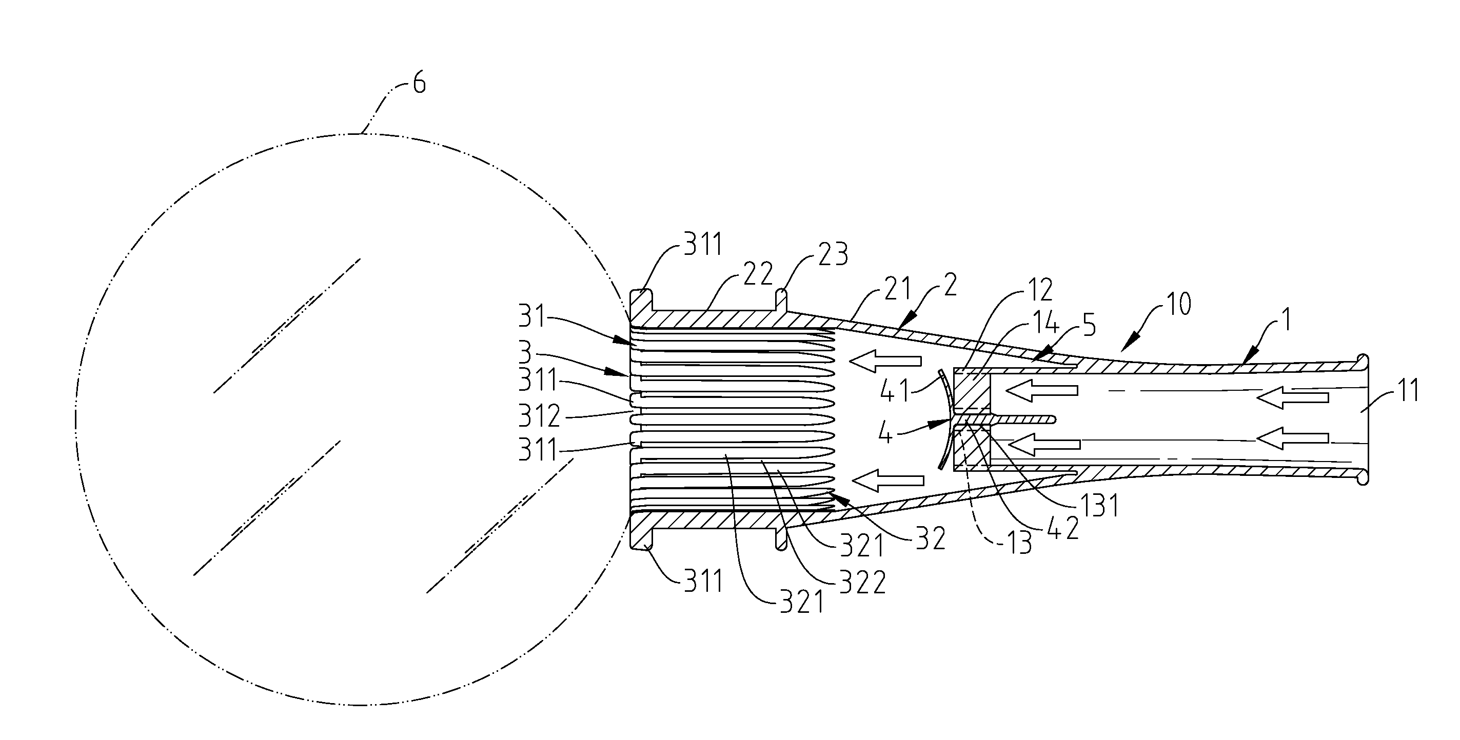
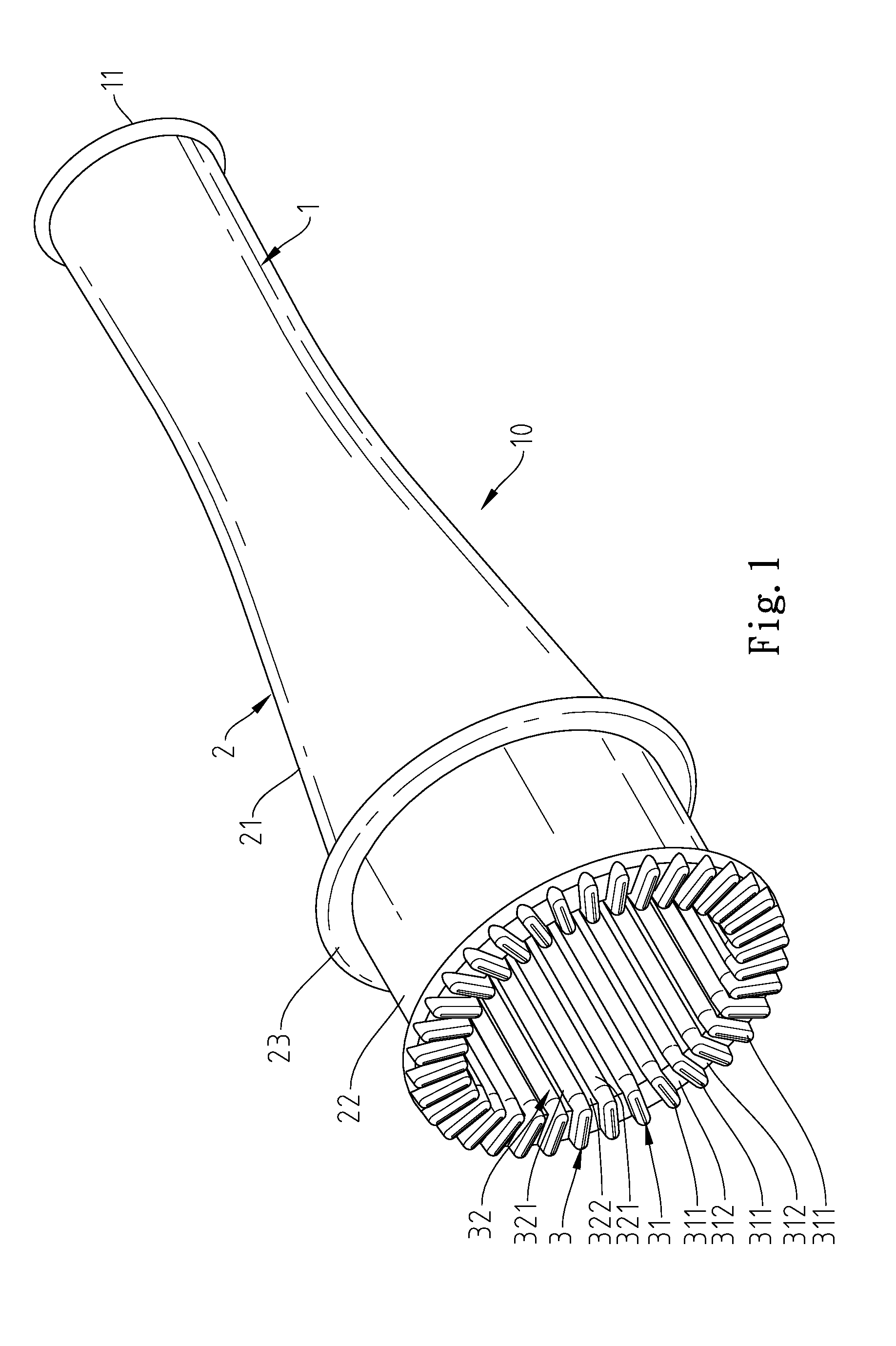
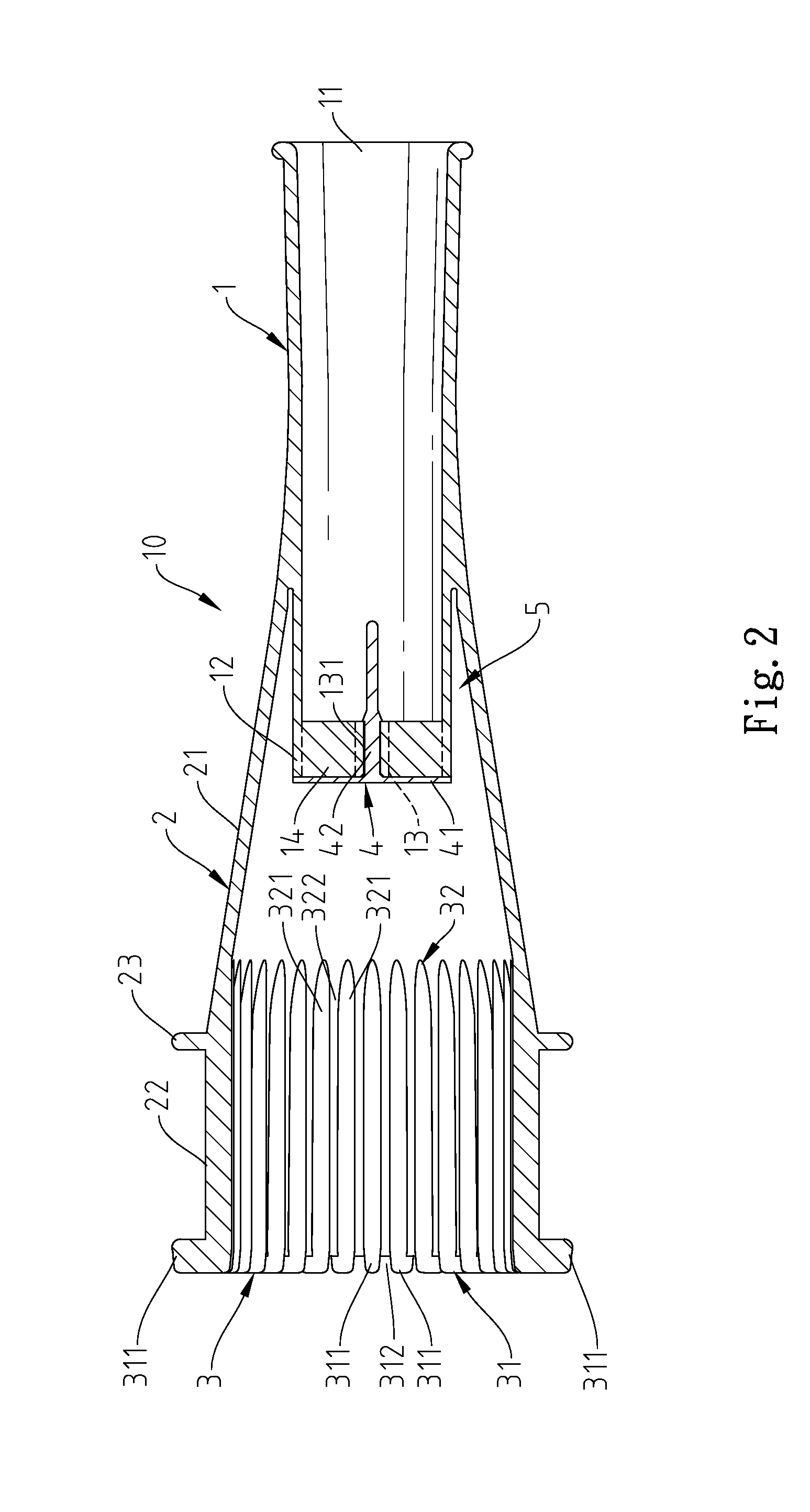
[0014]Referring to FIGS. 1-3, a bubble blower tube 10 in accordance with the present invention is shown. The bubble blower tube 10 comprises a blower tube 1, a bubble-forming tube 2, a bubble fluid retaining ring 3, and a check valve 4.

[0015]The blower tube 1 comprises opposing mouthpiece 11 and air outlet 12, a positioning member 13 mounted in the air outlet 12 and defining therein a positioning hole 131, and a rack 14 connected between the periphery of the positioning member 13 and the inside wall of the air outlet 12.

[0016]The check valve 4 comprises an elastically deformable flap 41 stopped at the outlet 12 of the blower tube 1, and a positioning rod 42 perpendicularly extended from the center of the bottom wall of the deformable flap 41 positioned in the positioning hole 131 of the positioning member 13.

[0017]The bubble-forming tube 2 comprises a rear end, namely, the connection end 21 integrally connected to the periphery of the blower tube 1 in a flush manner, a front end, na...


PUM


Abstract

A bubble blower tube includes a blower tube defining opposing mouthpiece and an outlet, a check valve mounted in the outlet to prohibit flowing of air or bubble fluid from the outlet toward the mouthpiece, a bubble-forming tube having a connection end connected to the periphery of the blower tube and a bubble-forming end shaped like a trumpet and suspending outside the blower tube, and a bubble fluid retaining ring located at the bubble-forming end of the bubble-forming tube and defining an outer bubble fluid retaining part and an inner bubble fluid retaining part.

Description

BACKGROUND OF THE INVENTION[0001]1. Field of the Invention[0002]The present invention relates to bubble blowers and more particularly, to a bubble blower tube, which prohibits reverse flow of air or bubble fluid.[0003]2. Description of the Related Art[0004]A bubble blower tube is a tubular tool for blowing bubbles. U.S. Pat. No. 4,166,336 discloses a bubble blower entitled “Bubble forming device”, which is made in the form of a funnel which is open at both ends. The small end serves as the mouthpiece, and the large end serves as the forming site for bubbles. The bubble forming end is configured so that a plane which is generally defined by the lip of the large end of the funnel extends at an acute angle to the longitudinal axis of the funnel. A film material supply surface is provided at the bubble forming end of the device. However, this design of bubble blowing device has drawbacks as follows:1. This design of bubble blowing device is mostly used for performances. After formation ...

Claims


Application Information

Patent Timeline
IPC IPC(8): A63H33/28
CPCA63H33/28
Inventor LIN, SHAU-CHI
Owner LIN SHAU CHI
Why Eureka
Try Eureka