DIN Rail Latching Arrangement

a latching arrangement and din rail technology, applied in the direction of substation/switching arrangement details, coupling device connections, electrical apparatus, etc., can solve the problems of complex detachable mounting of electrical/electronic devices onto the din rail, failure to prevent unintended disengagement of terminal blocks/electrical/electronic devices from the din rail, and high cost of connectors and latching arrangements

Active Publication Date: 2014-07-17
ASCO POWER TECH LP
View PDF9 Cites 20 Cited by
  • Summary
  • Abstract
  • Description
  • Claims
  • Application Information

AI Technical Summary

Benefits of technology

[0018]Still another object of the present invention is to provide a latching arrangement that can be used for all control room equipment and in applications where vibration requirements are stringent.

Problems solved by technology

However, detachably mounting of the electrical / electronic devices onto the DIN rail is complicated.
However, most of the connectors and latching arrangements for detachably securing the DIN rail terminal blocks / electrical / electronic devices onto the DIN rail that are known in the prior art are expensive and fails to prevent unintended disengagement of the terminal blocks / electrical / electronic devices from the DIN rail.

Method used


Image

  • DIN Rail Latching Arrangement
  • DIN Rail Latching Arrangement
  • DIN Rail Latching Arrangement

Examples


Embodiment Construction

[0053]The disclosure will now be described with reference to the accompanying drawings which do not limit the scope and ambit of the disclosure. The description provided is purely by way of example and illustration.

[0054]The embodiments herein and the various features and advantageous details thereof are explained with reference to the non-limiting embodiments in the following description. Descriptions of well-known components and processing techniques are omitted so as to not unnecessarily obscure the embodiments herein. The examples used herein are intended merely to facilitate an understanding of ways in which the embodiments herein may be practiced and to further enable those of skill in the art to practice the embodiments herein. Accordingly, the examples should not be construed as limiting the scope of the embodiments herein.

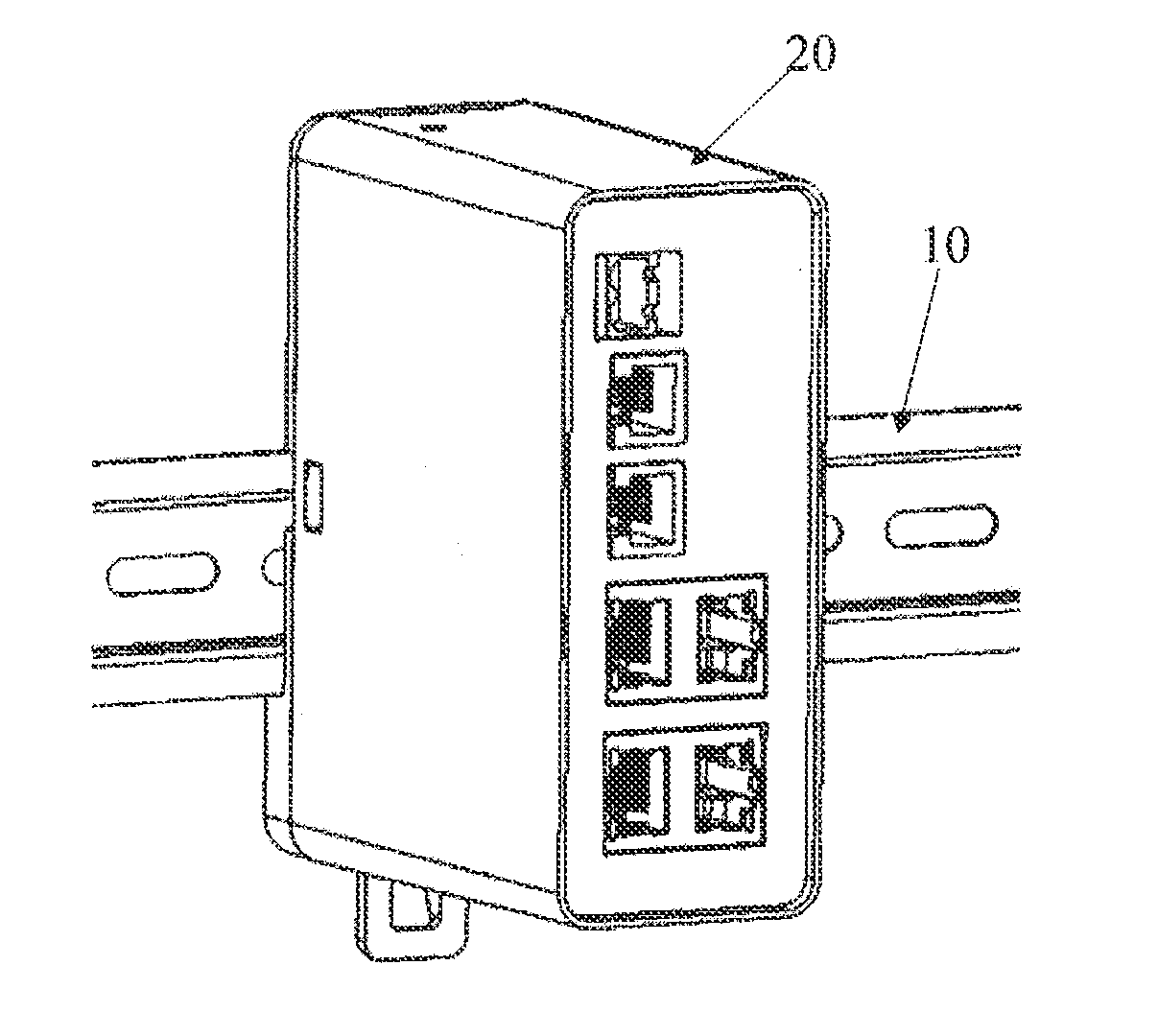
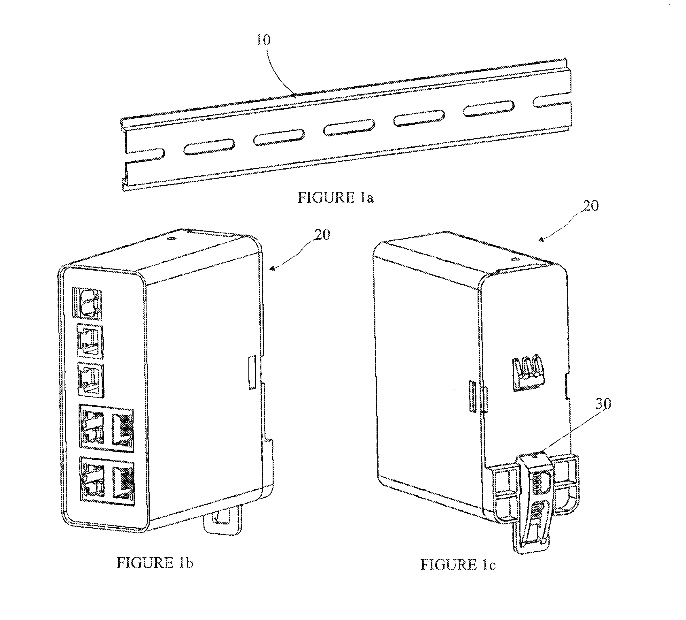
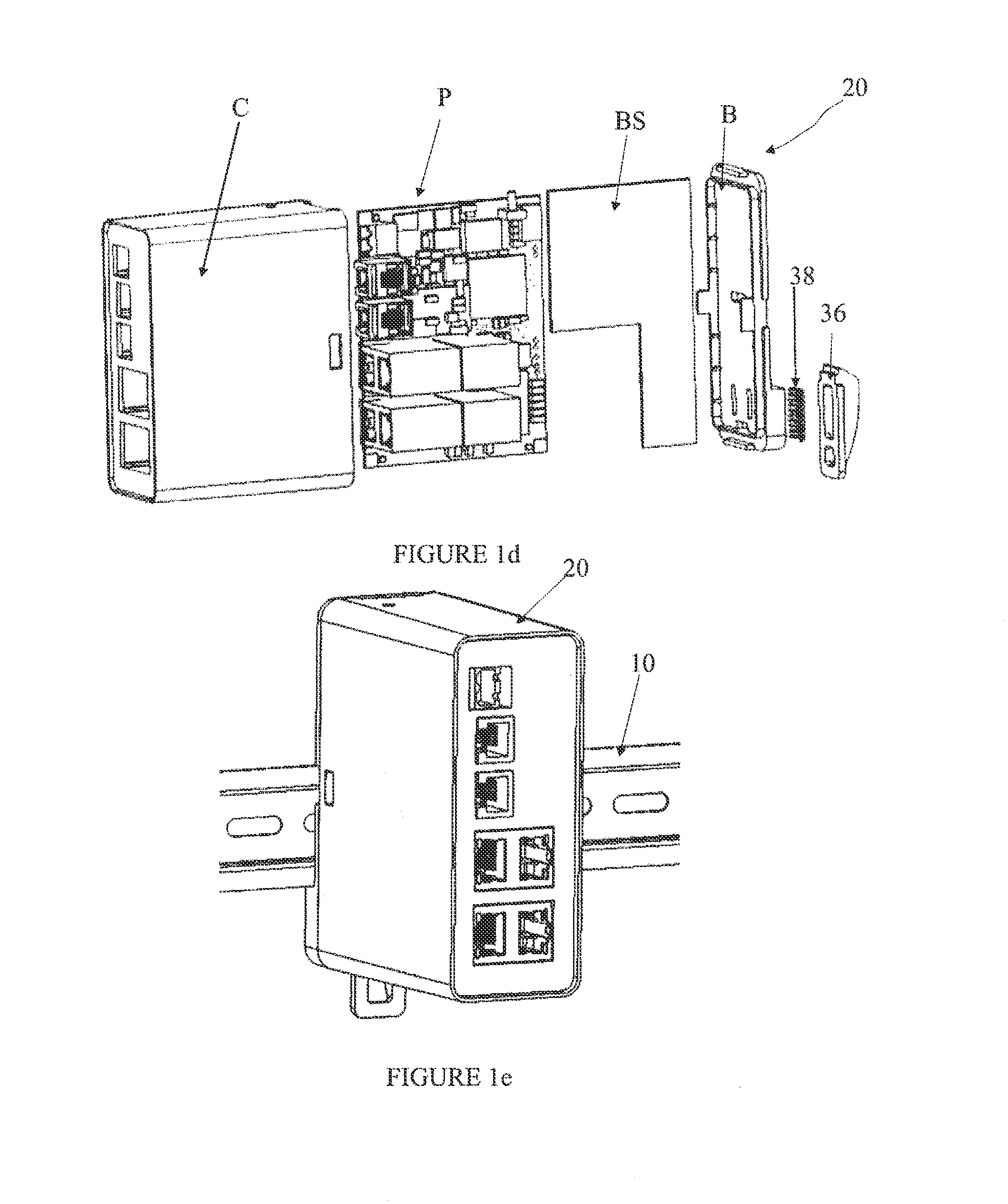
[0055]The present disclosure envisages a latching arrangement used for detachably mounting electrical / electronical / electronic devices such as circuit brea...


PUM


Abstract

A latching arrangement for detachably mounting a device on a DIN rail. A support member configured to be mounted on the DIN rail. A guiding slot configured on a same side of the device on which the support member is configured. An engaging lug received in the guiding slot and adapted to move between an engaging, extended configuration and a retracted, disengaging configuration. An urging element cooperating with the engaging lug and the device, the urging element adapted to be configured between a first operative configuration in which the urging element urges the engagement lug towards the support member and a second operative configuration in which said urging element is moved to facilitate moving of the engaging lug away from said support member.

Description

FIELD OF THE DISCLOSURE[0001]The present disclosure relates to a latching arrangement. More particularly, the present disclosure relates to a latching arrangement secured to electrical / electronical / electronic devices for detachably mounting the electrical / electronical / electronic devices onto a DIN rail.DEFINITIONS[0002]DIN rail is a metal rail widely used for mounting electrical / electronical / electronic devices such as circuit breakers and industrial control equipment, more particularly, DIN (Deutsches Institut far Normung) rail is an elongated conductive channel shaped member having side edge flange portions there-along to which connector engagement is made.BACKGROUND[0003]A large number of electrical / electronic / electronic devices / terminal blocks such as circuit breakers and industrial control equipment may be detachably mounted on a DIN rail. Most of the electrical / electronic devices are provided with a variety of latching arrangements for facilitating detachably mounting of the el...

Claims


Application Information

Patent Timeline
Patent Type & Authority Applications(United States)
IPC IPC(8): H01R25/14
CPCH01R25/14H01R9/2608H02B1/0523
Inventor DEVANAND, GOLESANDEEP, PATILDANGAT, ATUL
Owner ASCO POWER TECH LP
Why Eureka
Try Eureka